
A Windfarm Wireless Deployment Example in Practice
See a windfarm wireless deployment example built for turbine data, crew access, and backhaul continuity across changing terrain and weather conditions.


A windfarm wireless deployment example is most useful when it starts with the operational problem, not a radio datasheet. Consider a 60-turbine onshore site spread across rolling terrain, with a substation at one edge of the property, intermittent fiber availability, and maintenance crews moving between turbines daily. The network must carry SCADA traffic, condition-monitoring data, security video, voice, contractor access, and backhaul from remote field assets without introducing a single point of failure.
For this type of site, wireless is not simply a substitute for cable. It is an engineered transport layer that must account for turbine movement, terrain obstruction, weather exposure, spectrum availability, traffic priority, power resilience, and future expansion. The right design depends on those conditions.
The Operating Requirements Behind the Design
A windfarm network carries traffic with different consequences when it is delayed or lost. Turbine control and supervisory data generally require predictable, low-latency paths and clear traffic separation. Condition-monitoring systems can generate steady volumes of vibration, temperature, and gearbox data. Video surveillance may consume substantial bandwidth in bursts, especially during an incident. Field personnel also need secure connectivity for work orders, manufacturer portals, and communications.
A practical design separates these services into defined network segments and applies quality-of-service policies at the edge. SCADA and operational technology traffic receive priority over administrative or guest traffic. Video is managed so it does not consume the capacity needed for control systems. Contractor devices are isolated from turbine controls and utility operations.
The wireless architecture must also support the reality of wind operations. Turbines are tall structures, but they are not automatically ideal relay sites. The nacelle moves, the rotor creates variable RF conditions, and tower-mounted equipment can be difficult to service. A path that looks clear on a static map may lose margin when foliage, construction equipment, precipitation, or seasonal atmospheric conditions change.
Windfarm Wireless Deployment Example: Site Architecture
In this example, the substation serves as the primary network hub. It contains the core switching, security gateway, network management platform, and the primary connection to the utility or enterprise wide-area network. Two geographically separate backhaul paths leave the substation: a preferred fiber circuit where available and a licensed microwave path to a regional point of presence. The microwave path is not treated as an afterthought. It is engineered with sufficient capacity and availability targets to carry priority operations if the fiber service is unavailable.
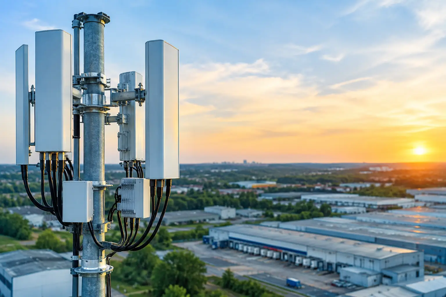
From the substation, the windfarm is divided into four wireless sectors based on terrain, turbine density, and line-of-sight conditions. Rather than attempting to reach every turbine with one long-distance link, the design uses strategically positioned aggregation locations. These may be operations buildings, meteorological towers, dedicated poles, or selected turbine-adjacent sites where mounting, power, access, and RF geometry support the role.
Each aggregation location establishes protected point-to-point or point-to-multipoint links to the hub and nearby turbine groups. Ring or partial-ring topologies are used where the geography permits. If a primary route is interrupted by equipment failure or a damaged cable segment, traffic can reroute through an alternate aggregation path. A simple star topology may cost less initially, but it can make an entire section of the windfarm dependent on one radio, one mount, or one path.
At each turbine, an industrial edge enclosure connects the local SCADA interface, condition-monitoring equipment, cameras, and approved Wi-Fi or private cellular access points. The enclosure includes managed switching, surge protection, environmental hardening, and power conditioning suited to the local electrical design. Network access controls prevent a service laptop or contractor device from becoming an unmonitored bridge into the operational network.
Why Auto-Aiming and Stabilization Matter
Fixed wireless links can perform well at a stationary windfarm site, but alignment tolerance still matters. Tall mounts are subject to wind loading, thermal movement, vibration, and structural deflection. On sites with mobile maintenance platforms, temporary cranes, offshore service vessels, or moving field assets, the challenge becomes more demanding.
Auto-aiming antenna systems reduce the operational burden of maintaining precise alignment across changing conditions. A tracking system can maintain the intended path instead of depending on manual adjustment after movement or weather events. Stabilized microwave systems become particularly relevant when backhaul must connect to a moving vessel, mobile command vehicle, or temporary offshore work platform supporting wind operations.
This is where engineered integration matters more than individual components. Antenna mechanics, radio compatibility, tracking behavior, link calculations, mounting design, and network failover must work together. BATS Wireless approaches these deployments as complete communications systems, not as a collection of radios installed wherever space is available.
Capacity Planning That Reflects Real Traffic
Capacity planning should begin with traffic measurements and operational growth assumptions. A common mistake is designing around the current SCADA load alone. That load may be modest, but the site can quickly add high-resolution cameras, turbine analytics, drone operations, remote expert support, and private 4G or 5G coverage for crews.
In this example, the design reserves capacity for operational control traffic first, then sizes the backhaul for expected monitoring and video demand with headroom for incident conditions. Video retention strategy matters. If cameras stream continuously to an off-site security operations center, the transport requirement is far higher than a design that records locally and sends event-based clips or lower-rate monitoring streams upstream.
Licensed microwave is often appropriate for the highest-value backhaul paths because it offers protected spectrum and more predictable interference management. Unlicensed or lightly licensed bands can be effective for shorter distribution links, provided the RF survey identifies noise sources and the design includes adequate fade margin. There is no universal band plan for every windfarm. Terrain, local spectrum congestion, link distance, capacity needs, and permitting requirements determine the right mix.
Security and Network Segmentation at the Edge
A windfarm wireless system must be designed as critical infrastructure. Encryption over the air is necessary, but it is only one layer. The network should enforce separation between corporate IT, contractor access, video systems, and operational technology. Device authentication, role-based access, firewall policy, logging, and remote management controls should be defined before field commissioning.
The most effective approach is to establish trusted zones. Turbine control networks should communicate only with approved supervisory systems. Maintenance access should be time-limited and logged. Cameras should have dedicated bandwidth policies. Management interfaces for radios, switches, and cellular equipment should be inaccessible from general user networks.
Remote management is equally important. Field teams need visibility into link quality, throughput, packet loss, radio temperature, power status, and path availability before dispatching a technician. A network that can identify a degrading link early is less likely to become an emergency truck roll during a storm or high-wind maintenance window.
Field Engineering Determines Long-Term Performance
The radio path is only one part of deployment readiness. A serious site survey evaluates topography, Fresnel-zone clearance, tower loading, grounding, cable routing, power availability, access restrictions, crane requirements, and maintenance safety procedures. It also considers whether future turbine additions or balance-of-plant assets will change the RF environment.
Installation details have outsized consequences. Poor connector weatherproofing, insufficient surge protection, unsuitable mounting hardware, and ignored cable strain relief can turn a well-designed link into a recurring fault source. Equipment selection should match the temperature range, wind exposure, salt exposure where applicable, and service-access constraints of the site.
Commissioning should validate more than basic connectivity. Teams should test primary and alternate paths, confirm failover timing, measure throughput under load, verify segmentation policies, document antenna alignment, and establish baseline performance values. Those baselines make later troubleshooting far more efficient.
When Private LTE or 5G Belongs in the Plan
Private LTE or 5G is not a replacement for every fixed wireless link. It is most valuable where personnel, vehicles, sensors, and mobile equipment require managed coverage across the windfarm. A private cellular layer can support field tablets, push-to-talk communications, connected safety systems, mobile inspection tools, and selected IoT devices while providing centralized authentication and mobility management.
The fixed microwave and wireless backhaul layer still carries that cellular traffic from distributed radios to the core. In other words, private cellular solves the access problem for moving users; engineered backhaul solves the transport problem. Combining both can provide better operational coverage than relying on public cellular service, particularly in remote regions where coverage and uplink capacity vary.
A successful windfarm deployment begins with a question that is more specific than, “Which radio should we buy?” Ask which communications services must remain available during a fiber outage, a severe weather event, or a critical maintenance operation. That answer should shape every path, antenna, enclosure, and failover decision that follows.

November 12, 2026

November 12, 2026

November 12, 2026
November 12, 2026
