
Auto Aiming Microwave Antenna System Explained
Learn how an auto aiming microwave antenna system maintains link performance on moving and remote assets in harsh, high-stakes environments.


When a vessel rolls, a command vehicle relocates, or a temporary site shifts priority overnight, the link budget does not care about the reason. It only reflects alignment, path quality, interference, and uptime. That is where an auto aiming microwave antenna system earns its keep. It removes the dependence on manual pointing and constant field intervention, replacing it with active tracking, calculated alignment, and repeatable performance in operating conditions where fixed wireless links usually struggle.
For organizations responsible for continuity in defense, maritime, public safety, oil and gas, and industrial connectivity, the issue is not simply getting a microwave link on the air. The issue is keeping it on target while assets move, vibration changes the geometry, and the RF environment refuses to stay static. In those cases, antenna performance is only one part of the equation. The tracking method, stabilization approach, radio integration, and network design all determine whether the system behaves like infrastructure or a recurring service problem.
What an auto aiming microwave antenna system actually does
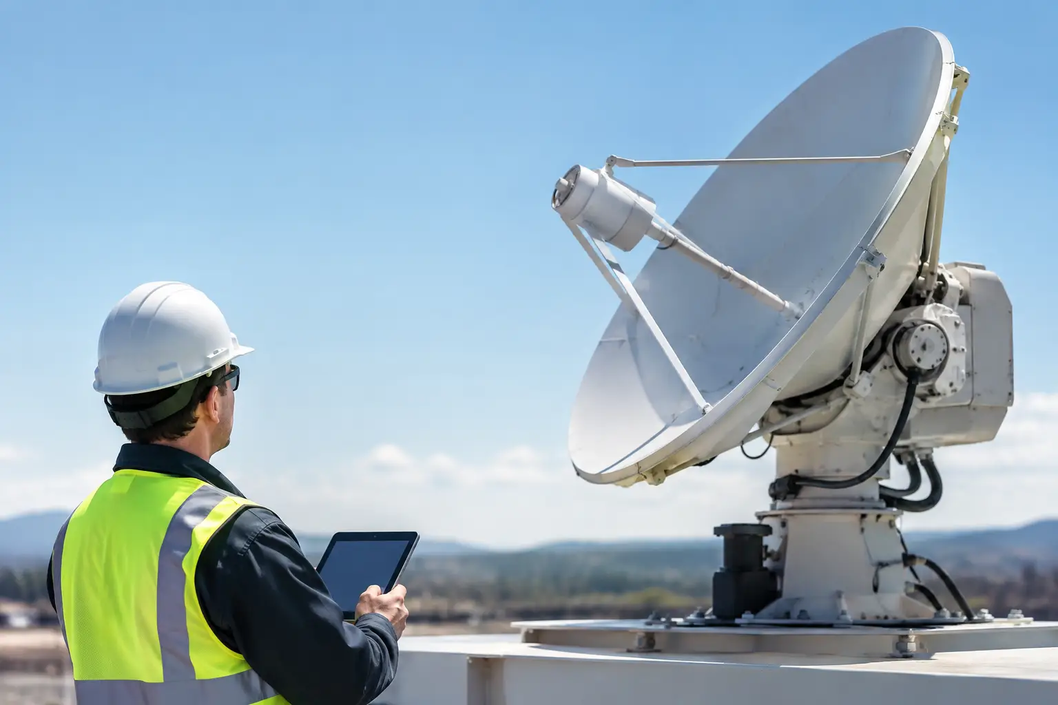
At its core, an auto aiming microwave antenna system automatically points and maintains a directional microwave antenna toward a designated target or network node. That sounds straightforward, but in field deployments the task is more complex. The system has to identify where the remote endpoint should be, move the antenna with enough precision to acquire the signal, and then hold alignment as conditions change.
That process typically combines motors, position sensors, control software, path calculation, and signal feedback from the connected radio. In stabilized systems, the platform also compensates for motion in multiple axes. On a moving vessel or vehicle, this is the difference between a useful broadband link and a signal that fades every time the platform changes heading or encounters rough conditions.
Not every system operates the same way. Some rely heavily on preloaded coordinates and heading data. Others use signal optimization loops to fine-tune final alignment. The best deployments use both. Calculated pointing gets the antenna close quickly, while live RF feedback helps maximize receive and transmit performance in real conditions.
Why auto aiming matters in operational networks
Manual alignment can work on static towers with easy access and stable geometry. It is far less attractive when the endpoint is mobile, remote, or difficult to reach. Sending technicians to re-aim antennas is expensive, slow, and often operationally disruptive. In some sectors, it is also unsafe.
An auto aiming microwave antenna system reduces those interventions. More importantly, it shortens restoration time after movement, relocation, or drift. For a public safety vehicle staging near an incident, a maritime vessel needing offshore connectivity, or a temporary industrial site requiring immediate backhaul, that speed has real value. Network availability affects command visibility, data transfer, voice quality, and application access.
There is also a planning advantage. Auto-aiming architectures make it more practical to extend broadband beyond conventional fixed plant. They support mobile and rapidly deployed communications strategies without treating mobility as an exception case. That changes how teams think about temporary sites, movable assets, and private network expansion.
The main components behind reliable auto aiming
A strong system starts with the antenna assembly itself, but precision mechanics matter just as much as RF performance. Drive systems need to move accurately and repeatedly, with minimal backlash and enough durability for continuous duty. If the mechanics are weak, theoretical pointing accuracy rarely survives field use.
Control logic is the next layer. The system needs to process heading, position, attitude, and target data fast enough to keep pace with movement. In stabilized microwave systems, inertial inputs are often critical because GPS position alone does not tell the full story. A platform can remain in the same general location while pitch, roll, and yaw make the antenna unusable without compensation.
Then there is radio compatibility. In practical deployments, the antenna system cannot be treated as an isolated device. It has to work with the selected microwave radio, modem, or integrated network stack, and it has to support the performance objective of the broader architecture. That includes throughput targets, latency tolerance, frequency planning, modulation behavior, and management visibility.
Environmental protection matters too. A laboratory-grade tracker is not the same as a field-ready system. Salt exposure, dust, vibration, temperature swings, and shock all affect long-term reliability. Buyers in mission-critical sectors should pay close attention to enclosure design, material choices, and maintenance expectations, not just peak gain or tracking speed.
Auto aiming microwave antenna system use cases
The strongest use cases are the ones where static infrastructure alone cannot meet the mission. Maritime operations are a clear example. Vessels need persistent communications for operational data, crew welfare, video, and remote system access, but vessel motion constantly challenges directional links. Auto-aiming and stabilized antennas make shore-to-ship and vessel-based backhaul far more practical over microwave and LTE-connected architectures.
In defense and public safety, mobility is often the requirement, not the exception. Tactical command vehicles, rapidly deployed surveillance assets, and incident response units benefit from microwave links that can acquire quickly and remain aligned during movement or repeated repositioning. The value here is not only uptime. It is reduced setup time and less dependency on highly specialized field alignment every time the asset moves.
Industrial and energy sites face a different version of the same problem. Temporary construction zones, remote oil and gas operations, windfarm support areas, and aquaculture facilities often need broadband where fiber is unavailable or too slow to deploy. An auto aiming microwave antenna system allows teams to create high-capacity backhaul connections in places where fixed alignment is difficult to maintain or frequent relocation is part of normal operations.
Where buyers should look past the specification sheet
Many evaluations start with gain, frequency range, and tracking speed. Those are necessary, but they do not tell the whole story. The harder questions are operational.
How fast can the system reacquire after a blockage or heading change? How well does it hold alignment under vibration? What happens when GPS quality drops, multipath increases, or the platform experiences aggressive movement? Can the controls integrate cleanly with existing radios and network management tools? Those details usually determine field performance more than the headline specifications.
It also pays to examine installation realities. Some systems look good on paper but require extensive custom mounting, power conditioning, or software work to become operational. Others are easier to integrate but may sacrifice flexibility. There is always a trade-off between speed of deployment, mechanical complexity, and ultimate performance envelope.
A solution-led vendor will usually address these trade-offs early. That includes path analysis, mounting strategy, radio pairing, expected coverage behavior, and maintenance planning. For buyers managing critical communications, that engineering support is often as important as the hardware.
Design trade-offs in mobile microwave tracking
There is no single best configuration for every deployment. High-gain antennas can extend range and improve link margin, but they generally require tighter pointing accuracy. That can increase mechanical and control demands, especially on moving platforms. A broader beam can be more forgiving, but range and capacity may suffer.
Stabilization depth is another example. A lightly mobile ground platform may need less correction than a marine deployment operating in rough water. Overbuilding the system can increase cost and complexity. Underbuilding it leads to dropped links, frustrated operators, and truck rolls that erase any savings.
Network architecture matters as well. In some cases, microwave should serve as the primary backhaul. In others, it works better as part of a layered design with private LTE, 5G, onboard networking, or failover paths. The right answer depends on geography, asset movement, spectrum conditions, and the consequence of downtime.
What successful deployment looks like
A successful deployment does not begin with the antenna on the mast. It begins with the path, the use case, and the operational constraints. Engineers should understand the movement profile of the asset, line-of-sight limitations, mounting conditions, power availability, and the applications that the link must support.
From there, system design should focus on the entire communications chain. That means antenna tracking, stabilization, radio selection, network topology, and support model. Companies like BATS Wireless operate in that space because high-stakes connectivity rarely fails for one reason alone. It fails at the boundaries between RF design, mechanical integration, and day-to-day operations.
The best result is a system that operators do not have to think about constantly. It acquires, holds, and restores the link with predictable behavior. It fits the platform, supports the applications, and reduces the need for manual correction in the field. That is what buyers are really purchasing when they invest in auto-aiming infrastructure.
If your network has to perform beyond fixed sites and ideal conditions, the question is not whether automation is useful. The question is whether your current approach can maintain alignment, capacity, and uptime when the environment starts working against you.
September 20, 2026

September 20, 2026

September 20, 2026
September 20, 2026
