
How to Configure CBRS Radio Equipment Correctly
Learn how to configure CBRS radio equipment for private LTE and 5G networks, from SAS onboarding to RF design, validation, and field performance checks.

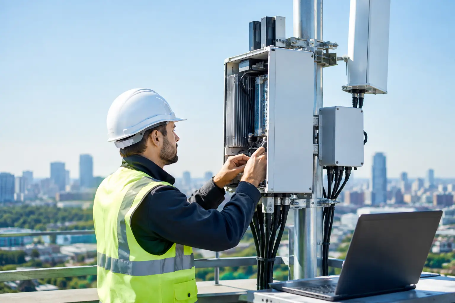
A CBRS deployment can look complete on a rack diagram and still fail at the edge of the coverage area, on a moving platform, or during its first SAS grant renewal. To configure CBRS radio equipment correctly, engineering teams need to treat the radio as one component in a coordinated RF, transport, timing, security, and spectrum-management system. The configuration file matters, but so do antenna placement, backhaul capacity, installation quality, and the operational behavior of the site.
For private LTE and 5G networks serving industrial facilities, ports, maritime assets, public safety operations, energy sites, and remote field teams, the objective is not simply to bring a CBSD online. The objective is predictable service under actual operating conditions.
Start With the CBRS Network Architecture
Before applying settings to a CBRS radio, confirm what the site is designed to accomplish. A fixed industrial yard, a warehouse campus, a mine, and a vessel-supported offshore operation may all use Band 48 spectrum, but they place different demands on coverage geometry, mobility, interference control, and transport resilience.
Define the radio role first. Is the unit providing broad outdoor coverage, targeted sector capacity, a point of presence for a private LTE core, or service for mobile vehicles and personnel? That decision affects antenna selection, transmit power, downtilt, channel planning, and where the radio should physically sit in the network.
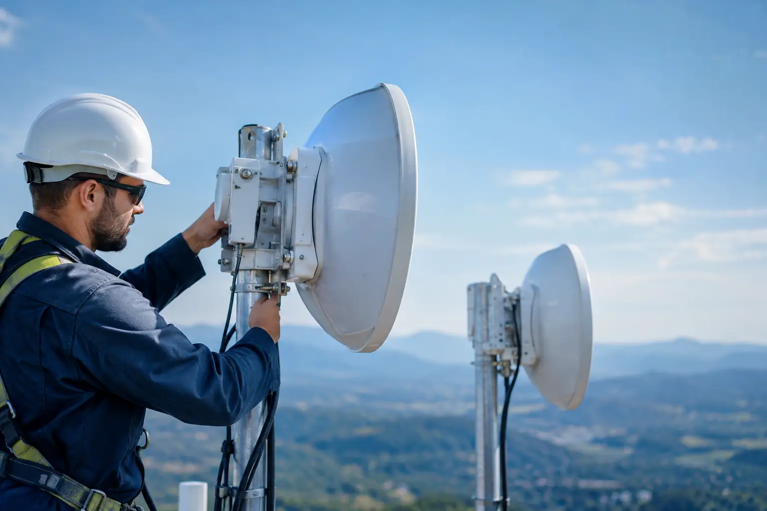
The transport path must be equally clear. A CBRS radio needs reliable Ethernet connectivity to the core network and its Spectrum Access System, or SAS. If the location depends on microwave backhaul, satellite, or a moving long-range wireless link, assess bandwidth, latency, packet loss, and failover behavior before commissioning the radio. A radio can be properly configured and still provide poor subscriber performance when its backhaul is oversubscribed or unstable.
For demanding sites, separate management traffic from user traffic where practical. Use defined VLANs, documented IP addressing, and access controls that allow operations teams to diagnose the radio without exposing the management interface to general network traffic.
Prepare the Site Before Powering the Radio
CBRS equipment must be installed according to the approved design, not adjusted later to suit the easiest mounting point. Height, azimuth, mechanical downtilt, cable routing, grounding, and line-of-sight constraints all influence the RF result.
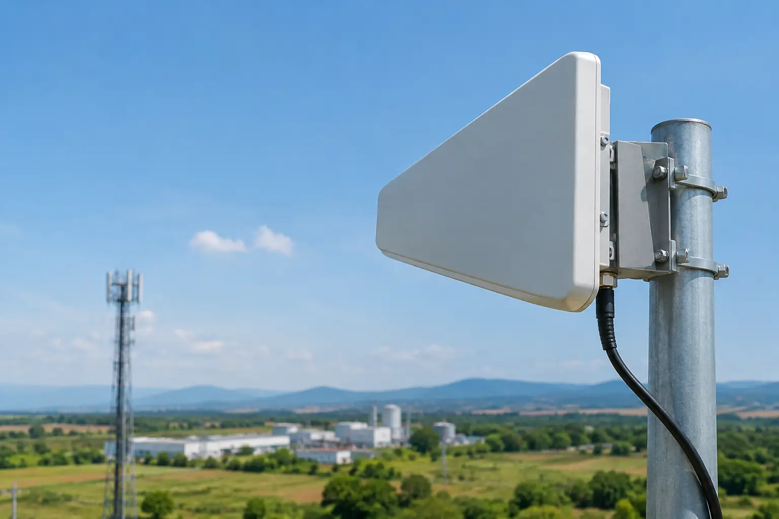
Confirm the antenna and radio combination is approved for the intended CBSD configuration. Integrated-radio antennas simplify installation but limit flexibility. External antenna systems provide more control over sector pattern, gain, and mounting location, but introduce feeder loss, connector exposure, and installation variables that must be accounted for in the link budget.
At fixed sites, record the precise latitude, longitude, and antenna height above ground level. These values are required during SAS registration and must reflect the actual installation. Do not rely on a preliminary design coordinate after the equipment has moved to a rooftop, tower face, or alternate equipment pad.
Grounding and surge protection deserve the same attention as RF settings. Industrial and maritime environments introduce corrosion, vibration, lightning exposure, generator transitions, and power-quality events that can create intermittent faults. Weatherproof every outdoor connection, provide proper grounding, and verify DC or PoE power margins under full load.
Configure CBRS Radio Equipment in the Right Order
A disciplined sequence prevents configuration conflicts and reduces time spent troubleshooting avoidable issues. Begin with the manufacturer-approved software version and a known baseline configuration. Record the radio model, serial number, firmware level, antenna configuration, MAC address, and assigned management address in the site documentation.
Establish management and timing
Configure the management interface with the correct static address, gateway, DNS settings where required, and VLAN tagging. Change default credentials, apply role-based access where supported, and restrict management access to approved administrative networks.
Timing is a critical dependency for LTE and 5G radios. Many CBRS platforms use GPS or GNSS as the primary timing source, with Precision Time Protocol or network timing as an alternate or holdover method. Verify the selected timing source, lock status, synchronization accuracy, and alarm behavior before placing the sector in service.
GNSS timing can be difficult on vessels, in dense industrial areas, or beneath structures that obstruct the sky. In those cases, the solution may require a remote GNSS antenna, a timing distribution design, or a radio platform with suitable holdover performance. Do not assume an IP connection alone provides timing adequate for coordinated cellular operation.
Complete SAS onboarding and registration
Every CBSD operating in the CBRS band must communicate with a certified SAS unless it is being staged in a controlled, non-radiating environment. Load the correct installation parameters, including the CBSD category, location, height, indoor or outdoor designation, antenna gain, azimuth, and downtilt.
The distinction between Category A and Category B equipment is operationally significant. Category A devices generally operate at lower power and are suited to many indoor or localized deployments. Category B devices support higher-power outdoor use but have more stringent professional installation and registration requirements. Select the category based on the approved design and equipment certification, not desired coverage alone.
Once registered, confirm the radio receives a grant and transitions to authorized transmit status. Watch the SAS response for assigned frequency range, maximum permitted EIRP, grant heartbeat status, and any denial or suspension messages. A grant does not guarantee that the radio can use the originally planned channel or power level at every location. Incumbent protection and nearby spectrum activity can change what is available.
Apply RF and cellular parameters
Set the operating bandwidth, channel assignment, transmit power limits, Physical Cell Identity, tracking area, and network identifiers in coordination with the private core and neighboring cells. The correct choices depend on network scale, device population, mobility needs, and spectrum granted by the SAS.
Avoid setting transmit power to the maximum simply because the equipment allows it. Higher EIRP can improve reach, but it can also increase interference, worsen overshooting into unwanted areas, and create poor uplink balance for handhelds or vehicle routers. The useful coverage boundary is usually determined by the weakest uplink device, not the radio’s downlink capability.
For multi-sector sites, coordinate azimuth, beamwidth, PCI planning, and overlap areas. Too little overlap can create mobility gaps. Too much overlap can lead to interference, unnecessary handovers, and difficult fault isolation. This is especially relevant where vehicles, vessels, cranes, or response teams move between sectors.
Validate the Core, Devices, and Backhaul Together
A CBRS sector showing green status is not yet an operational network. Confirm that the radio establishes its expected connection to the EPC or 5G core, receives the proper configuration, and accepts subscriber devices using the intended SIM or eSIM profiles.
Test both stationary and mobile endpoints. Verify registration time, authentication success, IP assignment, throughput, latency, packet loss, and handover behavior. Run tests at the center, edge, and known obstruction points of the service area. On industrial sites, include realistic conditions such as active machinery, loaded vehicles, closed metal doors, vessel motion, or personnel inside protective structures.
Backhaul testing should include sustained load, not only a brief speed test. Observe whether traffic prioritization protects operational applications such as voice, telemetry, video, command-and-control, or SCADA data when the link is busy. A private cellular network can carry multiple traffic classes effectively, but only when quality-of-service policies are aligned across the radio, transport network, and core.
Measure RF Performance, Then Tune It
Field validation should combine radio counters with physical measurements. Radio management data can reveal attachment failures, low signal quality, retransmissions, handover events, and sector loading. Walk tests, drive tests, or vessel-route testing show what users actually experience.
Key measurements commonly include RSRP for received power, RSRQ and SINR for signal quality, uplink and downlink throughput, latency, and handover success. No single number explains the whole network. Strong RSRP with poor SINR may indicate interference or excessive overlap. Good downlink speeds with weak uplink results may point to antenna gain, power balance, obstruction, or endpoint limitations.
Tune one variable at a time where possible. A change to antenna downtilt, power, bandwidth, or PCI strategy can affect multiple cells and make root-cause analysis harder if several adjustments are applied together. Maintain before-and-after records, including SAS grant details, timing state, weather conditions when relevant, and test-device location.
Build for Ongoing Operations
CBRS configuration is not a one-time commissioning task. SAS grants must remain active, firmware and security updates need controlled maintenance windows, and the RF environment can change as buildings, equipment, nearby systems, and operating patterns change.
Set alarms for timing loss, SAS heartbeat failure, grant suspension, high temperature, power events, backhaul degradation, and loss of core connectivity. Establish a practical escalation path so a field technician, network operations center, and engineering team can quickly determine whether an outage is caused by the radio, spectrum authorization, timing, transport, or core services.
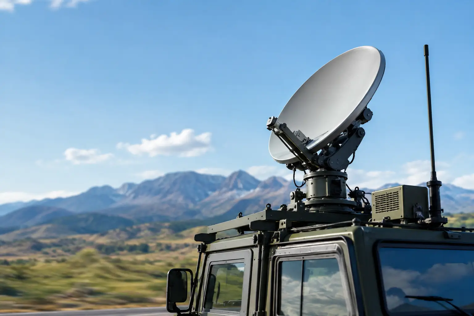
For mobile and remote deployments, keep a tested recovery configuration and a current record of installation parameters. If equipment is replaced after a storm, transport incident, or hardware fault, inaccurate coordinates or antenna data can delay return to service even when the replacement radio is available.
The strongest CBRS deployments are engineered around the mission rather than the radio menu. When RF design, stabilized or auto-aiming backhaul, spectrum authorization, core connectivity, and field validation are handled as one system, the result is a private wireless network that remains useful when the operating environment becomes difficult.
October 22, 2026

October 22, 2026
October 22, 2026
October 22, 2026
