
How to Align Long-Range Microwave Systems
Learn how to align long range microwave links with accurate path data, stable mounts, auto-aiming tools, and field verification for reliable backhaul.


A long-range microwave link can look healthy at commissioning and still become the weak point in an operational network weeks later. A few degrees of pointing error, an unstable mounting structure, or an unaccounted-for Fresnel obstruction can reduce fade margin enough to interrupt voice, video, SCADA, or private LTE/5G backhaul when conditions change. To align long range microwave systems correctly, field teams need more than a signal-strength reading. They need a verified path, a mechanically stable installation, and a process that confirms performance under real operating conditions.
Start With the Path, Not the Antenna
Microwave alignment begins before an installer touches the azimuth adjustment. Confirm the actual endpoint coordinates, antenna centerline heights, path distance, operating frequency, polarization, expected capacity, and required availability. These inputs determine the path budget and establish whether the link has enough margin for the operating environment.
Line of sight is necessary, but it is not enough. The Fresnel zone around the direct path must also remain substantially clear. Trees, cranes, drilling equipment, ship structures, seasonal vegetation, new buildings, and terrain can intrude into that zone even when the antennas remain visually visible to each other. At longer distances, small changes in antenna height or an overlooked obstruction can have a material effect on link quality.
A practical path review should account for the environment that exists during operations, not only the condition observed on installation day. For a maritime link, that includes vessel movement, mast flex, changing heading, and multipath reflections from the water. For oil and gas, it may include rotating equipment, process structures, and temporary construction activity. On construction sites and in disaster response deployments, the path may change frequently enough that reassessment should be built into the operating plan.
Establish the Performance Target
Define success before alignment begins. The target is not simply the highest received signal level. The link must meet a required receive signal level, modulation and coding scheme, throughput, latency, packet-loss threshold, and availability objective. A link pushed to its maximum modulation rate may deliver impressive bench results but leave inadequate fade margin for rain, atmospheric variation, movement, or interference.
The right target depends on the application. A video surveillance backhaul may prioritize sustained upstream capacity. A private 5G site may require predictable latency and headroom for multiple sectors. Command-and-control traffic may place availability ahead of peak throughput. Engineers should set acceptance thresholds that reflect the service carried by the network.
Build Mechanical Stability Into the Installation
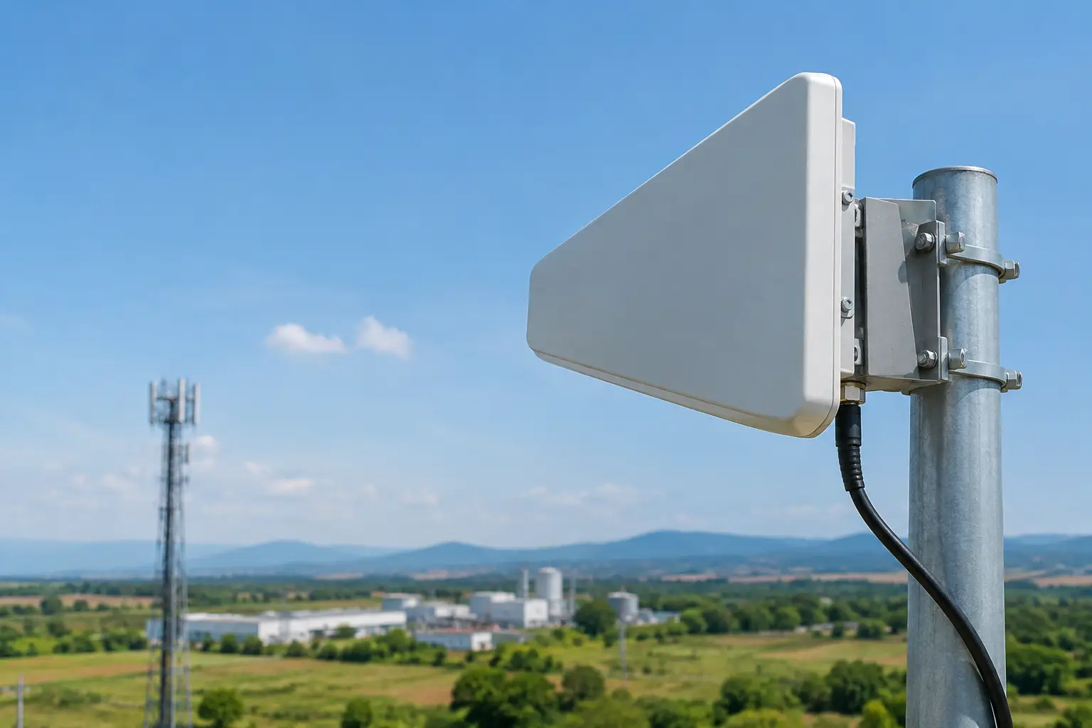
No amount of RF tuning can correct a mount that moves in the wind or flexes under load. High-gain microwave antennas have narrow beamwidths, particularly at higher frequencies and longer path distances. A minor physical shift at the antenna can create a meaningful pointing error at the far end.
Inspect the mounting structure, brackets, fasteners, mast condition, and cable strain relief before final alignment. The mounting surface must support the antenna’s wind loading and preserve its orientation through normal environmental stress. On mobile platforms, stability becomes a system-level requirement involving sensors, motion compensation, tracking software, and the antenna positioner.
Use calibrated installation tools where possible. A survey-grade compass or GNSS-derived bearing can establish initial azimuth, but magnetic compasses can be affected by steelwork, electrical systems, and local magnetic variation. Inclinometers and digital levels help establish elevation, yet they should be treated as a starting point rather than final proof of alignment. The radio’s received level, quality metrics, and error counters remain the operational reference.
Correct polarization is equally important. Cross-polarized antennas can lose substantial signal and create avoidable interference. Confirm the intended horizontal, vertical, or slant polarization at both ends of the path, then verify that the physical antenna orientation matches the radio configuration and link design.
Align Long-Range Microwave Links in Controlled Steps
Initial acquisition should be deliberate. Start from the calculated azimuth and elevation, use coarse adjustments to find the remote signal, then reduce the adjustment range as received level improves. If both sites are adjusted aggressively at the same time, teams can lose the path and spend unnecessary time reacquiring it. Coordinate the work through a single test plan, with one end held stable while the other performs fine adjustments.
Fine alignment requires more than watching received signal strength. Monitor received level, signal-to-noise ratio, modulation state, packet errors, and radio-specific quality indicators. A signal peak can be misleading if it comes with high interference or poor error performance. The best final position is the one that delivers stable quality across the full set of operational metrics.
After optimizing azimuth and elevation, recheck both because adjustment in one plane can affect the other. Then tighten hardware in stages and verify the readings after each stage. This prevents the common problem of achieving a clean peak, applying final torque, and finding that the antenna shifted during fastening.
For links using automatic transmit power control or adaptive modulation, record both instantaneous and stabilized readings. Adaptive systems can mask an alignment issue by reducing modulation or increasing power. The connection may remain up while delivering less capacity and less margin than the design requires.
When Manual Alignment Is Not Enough
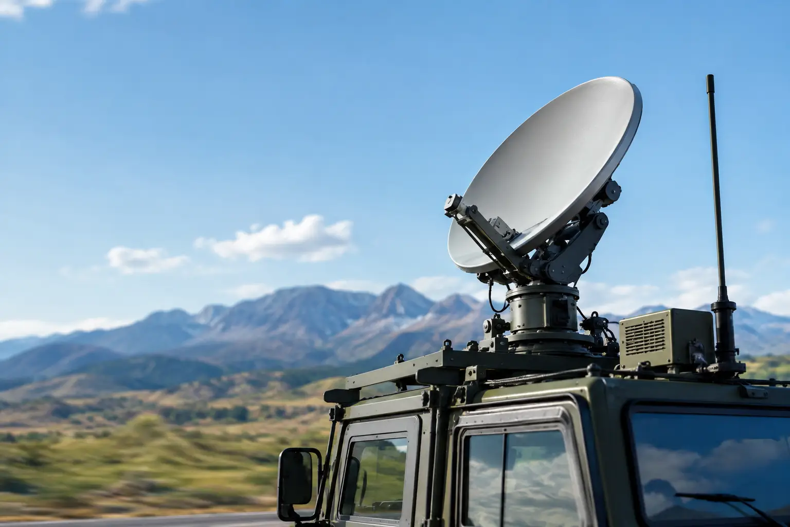
Manual alignment is effective for fixed, accessible links with clear paths and stable structures. It becomes less suitable when endpoints move, the operating area is exposed to vibration, or antenna beamwidths are extremely narrow. Ground-to-air communications, vessel connectivity, mobile command vehicles, and moving industrial assets require a different approach.
Auto-aiming antenna tracking systems continuously calculate the required look angle and compensate for position, heading, pitch, roll, yaw, or changing endpoint location. Stabilized microwave systems extend that capability where platform movement would otherwise disrupt the path. These systems are not a substitute for sound path engineering. They are the mechanism that maintains alignment after the original path has been engineered and commissioned.
BATS Wireless applies this approach where standard fixed-point microwave hardware cannot maintain the pointing accuracy required for operational continuity. The value is not only faster acquisition. It is sustained connectivity when the platform, terrain, or mission changes.
Verify the Link Under Operating Conditions
A completed alignment should be followed by a structured acceptance test. Confirm the expected throughput in both directions, latency, jitter where relevant, packet loss, modulation stability, and error rates. Review the radio event log for retrains, power changes, modulation step-downs, or synchronization events that may not be obvious during a short test.
Run the link long enough to expose issues that a quick field test misses. Thermal changes can affect equipment after startup. Wind can reveal mount movement. A vessel can experience a different motion profile after leaving harbor. Industrial interference sources may only appear during a production cycle. Where the link carries a critical service, test during representative traffic load rather than with an idle circuit.
Document the final configuration: antenna bearings, elevation angles, polarization, mount details, receive levels, transmit power, modulation, firmware versions, and acceptance-test results. This baseline makes future troubleshooting much faster. If performance degrades months later, operations teams can compare current values with known-good commissioning data rather than start from scratch.
Plan for Maintenance, Not Just Commissioning
Long-range microwave alignment is not a one-time activity in demanding environments. Inspect physical hardware after severe weather, vessel maintenance, tower work, collision events, or changes near the path. Monitor received level and modulation trends over time. A gradual decline may indicate antenna movement, water ingress, connector degradation, growing vegetation, or new obstruction rather than a radio fault.
For mobile and stabilized applications, validate tracking calibration, position inputs, heading sensors, and control-system alarms as part of preventive maintenance. An antenna can be mechanically sound while inaccurate motion data steadily points it away from the remote endpoint.
The field standard is simple: a microwave link is properly aligned only when its physical installation, RF measurements, capacity, and operational margin all agree with the engineered design. Treat alignment as a controlled commissioning process, and the network is far more likely to deliver when remote operations need it most.

October 22, 2026
October 22, 2026
October 22, 2026

October 22, 2026
