
Vehicle Mounted Antenna Guide for Mobile Networks
This vehicle mounted antenna guide explains mounting, RF design, stabilization, and testing for reliable mobile broadband in mission-critical operations.

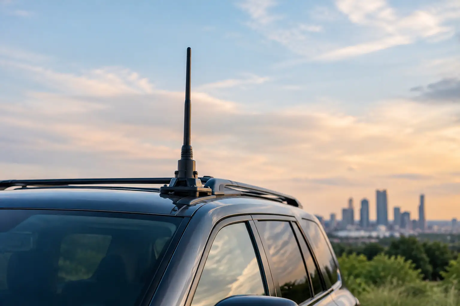
A vehicle can show full signal strength at a standstill and still lose its data path the moment it turns, climbs, hits rough terrain, or moves behind a ridge. That is why a vehicle mounted antenna guide must address more than selecting an antenna with the right frequency range. Mobile connectivity depends on the complete RF system: antenna placement, ground plane, cable loss, radio compatibility, power quality, network architecture, and the ability to maintain alignment while the platform moves.
For public safety fleets, defense vehicles, field-service trucks, utility operations, maritime support vehicles, and industrial mobile assets, the goal is operational continuity. The correct design keeps critical applications, voice, telemetry, video, and onboard users connected where standard cellular equipment or fixed wireless infrastructure cannot.
Vehicle Mounted Antenna Guide: Define the Mission First
Start with the communication path, not the antenna catalog. A vehicle that needs private LTE coverage across a refinery has different requirements from a command vehicle transmitting live video over microwave backhaul or a mobile work crew using public cellular networks. Frequency band, required throughput, coverage distance, vehicle speed, terrain, and network priority all affect the appropriate design.
The first decision is whether the vehicle is communicating with nearby terrestrial infrastructure, a distant fixed site, other vehicles, aircraft, or a satellite service. Omni-directional antennas generally suit local cellular, Wi-Fi, and private LTE/5G coverage because they maintain coverage around the vehicle. Directional antennas provide greater gain for long-range point-to-point links, but they must remain aimed at the remote endpoint. On a moving platform, that normally requires antenna tracking or stabilization.
Define what failure means in the operating environment. A brief video-quality reduction may be acceptable for a commercial inspection crew. A lost command-and-control link, emergency dispatch connection, or airborne surveillance feed may not be. This distinction determines redundancy, antenna diversity, radio configuration, and the need for an auto-aiming system.
Select the Antenna Type for the Radio and Link
Antenna selection starts with frequency support, but frequency alone does not establish performance. The antenna must match the radio’s operating bands, impedance, connector type, maximum power, and MIMO requirements. A wideband antenna can simplify fleet hardware, yet it may give up gain or pattern control compared with a purpose-built antenna for a defined band.
For cellular and private LTE/5G systems, multiple antenna elements are often required to support MIMO. These elements need physical separation and appropriate polarization to prevent correlation between paths. Mounting two or four antennas close together because the roof has limited space can compromise the very diversity the radio depends on.
GNSS antennas, Wi-Fi antennas, cellular antennas, and microwave systems also need to coexist without creating interference. High-power transmit systems can desensitize nearby receivers, especially when antennas are poorly separated or filtering is not considered. Onboard networks should be engineered as a system rather than assembled as independent devices.
Directional microwave antennas deserve particular scrutiny. High gain supports longer paths and higher-capacity backhaul, but a narrow beamwidth leaves little tolerance for vehicle movement. A parked vehicle may only need manual alignment. A moving vehicle, vessel, or platform that experiences pitch, roll, vibration, and heading changes requires a stabilized antenna system that continually calculates and corrects the pointing angle.
Treat the Vehicle Roof as Part of the RF Design
Mounting location changes the antenna pattern. On many vehicles, the roof is the preferred location for an omni antenna because it provides height, a clearer view of the horizon, and a more consistent metal ground plane. A center-roof position often produces a more symmetrical radiation pattern than a hood edge, bumper, mirror arm, or rear rack.
That rule is not absolute. A tall roof-mounted antenna may interfere with garages, bridges, tree cover, crane operations, or vehicle loading procedures. A low-profile antenna can protect the hardware but may provide less gain or reduced separation from other RF devices. The practical answer depends on clearance requirements, operating band, vehicle body material, and the priority of each link.
Nonmetal roofs require additional attention. Fiberglass, composite, and aluminum vehicle structures do not behave like a conventional steel ground plane. Some antennas include their own ground plane and are designed for this condition. Others require a metal mounting plate sized for the operating frequencies. Installing a ground-plane-dependent antenna on a composite roof without addressing this issue can distort coverage and increase reflected power.
Avoid placing antennas behind metal equipment, light bars, cargo racks, exhaust stacks, or cab structures that shadow the intended coverage area. Even a correct antenna can perform poorly when its line of sight is blocked in the direction that matters most.
Manage Cable Loss, Connectors, and Power
RF cable is not a passive afterthought. At higher frequencies, long or undersized coaxial runs can consume a significant portion of the gain gained through careful antenna selection. Cable length should be kept as short as practical, while still allowing strain relief, service access, and protected routing through the vehicle.
Use cable rated for the frequency, environment, and bend radius involved. Route it away from sharp edges, high-heat engine components, moving mechanisms, and sources of electrical noise. Grommets, weatherproof entry points, and properly supported cable runs prevent damage that may not be visible during a basic installation inspection.
Connector quality matters just as much. Loose, mismatched, or improperly terminated connectors introduce loss, reflections, and intermittent faults that are difficult to isolate in the field. Exterior connections require weather sealing and corrosion protection. On assets operating near saltwater, chemicals, dust, or extreme temperature cycles, connector protection is a reliability requirement rather than a finishing detail.
The vehicle power system also affects network performance. Mobile routers, radios, tracking systems, and onboard switches must tolerate voltage variation during cranking, charging, and equipment startup. Use appropriate power conditioning, fusing, grounding, and ignition-control design so the communications system does not reset when the vehicle needs it most.
Stabilization Is the Difference on Moving Long-Range Links
A fixed directional antenna assumes a fixed geometry. A vehicle does not provide one. Heading changes, suspension movement, uneven roads, wind loading, and platform roll continuously alter the antenna’s aim. As link distances increase and beamwidth narrows, even minor pointing errors can reduce throughput or break the connection.
Stabilized microwave systems solve this problem by combining positional data, motion sensing, path calculation, and motorized antenna control. Auto-aiming systems continuously maintain the link toward a known endpoint or track a moving target, depending on the mission. This makes high-capacity communications viable for applications such as ground-to-air connectivity, mobile command operations, maritime broadband, and long-range backhaul from remote worksites.
Stabilization should be selected according to platform dynamics. A road vehicle may need to compensate mainly for vibration and terrain movement. A vessel may require continuous correction for roll, pitch, yaw, and changing sea state. The antenna, drive assembly, tracking logic, and radio must be designed together to meet the expected availability target.
Build Redundancy Into the Network Architecture
The best antenna installation cannot compensate for a single-path network design in a difficult operating area. Mission-critical vehicles frequently benefit from multiple communications paths, such as primary microwave backhaul with cellular failover, dual-carrier cellular connections, or private LTE supported by satellite contingency service.
Network policy should determine which traffic uses each path. Safety communications, dispatch, remote control, and operational data should retain priority when capacity falls. Guest access, software updates, and noncritical traffic should not consume the bandwidth required for the mission. A properly integrated onboard network can apply these policies automatically while presenting a consistent connection to vehicle users and devices.
This is also where radio compatibility becomes essential. Antennas, routers, modems, and tracking platforms must support the same bands, interfaces, and management requirements. BATS Wireless designs these elements as complete mobile connectivity systems, reducing the risk of a technically valid but operationally fragile deployment.
Installation and Commissioning Must Be Measured
A clean installation is not proof of RF performance. Commissioning should include cable and connector inspection, antenna placement verification, grounding checks, radio configuration review, and measured link testing. For directional systems, verify alignment accuracy and reacquisition behavior after deliberate movement.
Test the vehicle in representative conditions. Drive the expected route, operate at realistic speeds, engage vehicle-mounted equipment, and test during the same types of motion the system will face in service. Measure signal quality, throughput, latency, packet loss, handoff performance, and recovery time after an obstruction or power cycle. If the system supports multiple paths, confirm that failover occurs at the intended thresholds and that critical applications remain available.
Document baseline results before field deployment. Those measurements give maintenance teams a reference when performance changes months later due to cable damage, antenna obstruction, network expansion, or a configuration update.
Maintain the System for the Environment It Faces
Vehicle-mounted communications equipment experiences vibration, weather, road debris, washdowns, and repeated thermal cycling. Routine inspections should look for loose mounts, damaged radomes, chafed cable jackets, corroded connectors, water ingress, and changes to roof equipment that could obstruct the antenna pattern.
For tracked systems, inspect moving assemblies, calibration status, and error logs on a scheduled basis. Firmware and network configurations should be managed through a controlled process, particularly on vehicles supporting public safety, defense, or industrial operations. A small mechanical or software issue is less costly to correct during planned maintenance than during a deployment.
The practical standard is simple: design the antenna system around the vehicle’s mission, then prove its performance under the conditions that mission creates. When the RF path, mounting strategy, tracking capability, and onboard network are engineered together, mobile assets can carry dependable broadband far beyond the reach of ordinary connectivity.
November 12, 2026
November 12, 2026

November 12, 2026

November 12, 2026
