
A Practical Guide to Mobile Antenna Stabilization
Use this guide to mobile antenna stabilization to specify tracking, inertial sensing, RF integration, and testing for reliable links in motion at sea.

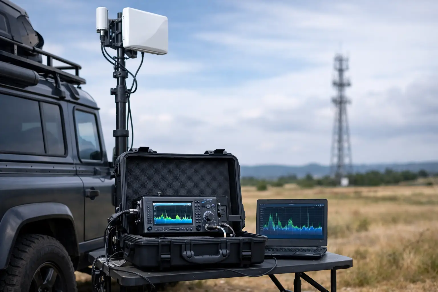
A link that performs perfectly from a fixed site can fail quickly when the platform starts moving. Vessel roll, vehicle vibration, changing heading, terrain, and acceleration all move the antenna away from its intended path. This guide to mobile antenna stabilization explains how to maintain usable RF alignment when connectivity cannot wait for the asset to stop.
For maritime operators, public safety teams, defense programs, and industrial fleets, stabilization is not an accessory. It is a core part of the wireless architecture. The right system protects link availability, supports usable throughput, and reduces the operational burden of manual antenna aiming in difficult conditions.
What Mobile Antenna Stabilization Actually Does
Mobile antenna stabilization keeps a directional antenna pointed at a remote endpoint while its host platform moves. Depending on the application, that endpoint may be a shore station, a microwave relay, another vehicle, an aircraft, or a satellite terminal. The system continually measures platform motion and commands the antenna positioner to compensate.
A stabilized system typically combines an antenna, pan-and-tilt or azimuth/elevation positioner, inertial measurement unit, GNSS receiver, control software, and radio equipment. On platforms with high motion or long-range links, these components must operate as one engineered system. A fast positioner alone cannot correct a poor heading reference, delayed sensor data, or an antenna that is undersized for the path.
The goal is not simply to keep the antenna moving. The goal is to keep the RF beam centered on the target with enough accuracy to preserve the fade margin required by the mission.
Stabilization, Tracking, and Auto-Aiming
These terms are related but not interchangeable. Stabilization compensates for local platform motion. Tracking follows a remote target whose position may also change. Auto-aiming generally refers to acquiring the target direction without a technician manually steering the antenna.
A patrol vessel holding a link to a fixed shore site may rely primarily on stabilization plus GPS-based pointing. Two moving vehicles exchanging a narrow-beam microwave link need tracking on both ends, often with continuous position exchange and path calculation. A ground-to-air application introduces another level of complexity because speed, altitude, heading changes, and geometry shift rapidly.
Start With the Link Requirement, Not the Antenna
The most common specification mistake is selecting hardware before defining the link. Stabilization performance is determined by the complete communications requirement: distance, frequency band, expected capacity, path availability target, platform dynamics, and physical installation constraints.
Begin by defining the remote endpoint and operating envelope. Is the endpoint fixed, moving, or intermittently available? Is the asset operating in open water, urban corridors, offshore fields, mountainous terrain, or a mixed environment? These questions determine whether the system needs simple position-based pointing, active signal-based tracking, or both.
Frequency selection matters immediately. Higher frequencies can deliver substantial bandwidth with compact antennas, but their narrower beamwidth demands tighter pointing accuracy. A small pointing error that has little effect on a lower-frequency, wider-beam system can create material signal loss at higher microwave bands. Rain attenuation, sea-surface reflections, and obstruction risk must also be included in the link budget.
Required availability should drive the engineering discussion. A noncritical construction-site link may tolerate brief degradation while the vehicle repositions. Command, control, emergency response, and operational data links usually require a larger margin, redundant paths, or failover to private LTE/5G, satellite, or another bearer.
Match Pointing Accuracy to Beamwidth
Beamwidth is the practical measure that connects antenna selection to stabilization performance. As antenna gain increases, the beam becomes narrower. Narrow beams improve range and interference rejection, but demand more accurate control.
A useful rule is to avoid designing around the minimum theoretical pointing requirement. The platform will not experience only clean, predictable motion. It will encounter sensor bias, GNSS variation, structural flex, vibration, backlash, wind loading, and temporary blockage. The system needs enough control precision and link margin to handle those conditions without repeated loss of lock.
For this reason, a high-gain antenna is not automatically the best answer. On a highly dynamic vessel or vehicle, a slightly lower-gain antenna with a wider beam and more forgiving acquisition characteristics can produce better operational uptime. It depends on range, capacity needs, and the severity of platform movement.
Understand the Motion Environment
Every platform generates a distinct motion profile. A workboat may experience continuous roll, pitch, yaw, and vibration. A ground vehicle may see sharp heading changes, suspension movement, terrain-induced shocks, and intermittent line-of-sight blockage. A crane, mining machine, or windfarm service vessel may also introduce structural movement between the sensor location and antenna mount.
The inertial measurement unit must be selected and installed for that reality. Its update rate, accuracy, latency, and calibration all affect pointing quality. A sensor mounted far from the antenna may report motion that does not fully represent the antenna’s own movement, particularly on flexible structures. Mounting geometry and structural stiffness are engineering inputs, not installation details to address later.
Control-loop response also matters. If the platform motion changes faster than the positioner can respond, the antenna will lag the target. Conversely, excessive controller gain can create oscillation, causing the system to hunt around the correct bearing. Proper tuning is essential, particularly where antennas carry meaningful wind load or operate on platforms with persistent vibration.
Design the RF and Mechanical Systems Together
A stabilized antenna system succeeds only when RF, mechanical, power, and network elements are planned together. The antenna mount must withstand shock, vibration, corrosion, and wind while maintaining alignment. Cable routing must allow full motion without binding, fatigue, or unacceptable RF loss. Radomes, where needed, should protect the system without introducing avoidable attenuation or changing the antenna pattern.
Power design deserves equal attention. Motors can draw significant current during acquisition and high-motion correction. A system that shares a poorly regulated supply with other onboard loads may reset, lose calibration, or introduce noise into sensitive equipment. Specify voltage range, surge protection, grounding, and battery backup according to the platform’s actual electrical environment.
Radio integration is another critical decision. The positioner controller and radio should share the information needed to acquire and maintain the link. Integrated radios may provide received signal information that helps confirm alignment, while network management data can identify a degrading path before users report an outage. Compatibility across antenna, mount, radio, controller, and network layer reduces field integration risk.
BATS Wireless approaches these deployments as complete stabilized microwave and tracking systems rather than disconnected hardware components. That distinction matters when the installation must perform across an entire operating lifecycle, not just during dockside acceptance testing.
Plan for Acquisition, Obstruction, and Recovery
A link will periodically lose a clear path. A vessel can pass behind a structure, a vehicle can enter a cut in the terrain, or the remote endpoint may temporarily be unavailable. The system’s recovery behavior often separates a workable deployment from one that consumes operator time.
Specify how the antenna should behave after signal loss. A position-based system may continue pointing to calculated coordinates until the path returns. An active tracking system may search around the predicted bearing using a controlled scan pattern. In either case, reacquisition time should be measured against the operational impact of an interruption.
Network architecture should support those events. A stabilized microwave path may be the primary high-capacity bearer, while private LTE/5G, satellite, or another radio path provides continuity during obstruction. Traffic policies should prioritize control, voice, telemetry, and critical applications when available capacity changes. Raw bandwidth is not the only metric that matters during a degraded condition.
Commissioning Is Where Assumptions Meet Reality
Factory testing validates components. Field commissioning validates the system. The commissioning plan should include static alignment, dynamic motion tests, path-loss verification, throughput testing, failover behavior, and monitoring validation. On maritime deployments, conduct tests across the sea states and headings that reflect normal operations when possible. On land, test the actual routes, turns, grades, and operating speeds that will challenge the link.
Do not accept a deployment based solely on an RSSI reading while the platform is stationary. Confirm received signal level, modulation behavior, packet loss, latency, jitter, reacquisition time, and positioner response under movement. Record baseline measurements so maintenance teams can distinguish normal variation from a developing mechanical, RF, or sensor issue.
Ongoing maintenance is practical risk management. Inspect mounts, fasteners, connectors, cable strain relief, seals, and corrosion protection on a schedule that matches the environment. Verify inertial sensor calibration and controller performance after hard impacts, equipment replacement, or structural work. A small mechanical shift can become a major service issue on a narrow-beam path.
The best mobile antenna stabilization design gives operators something valuable: communications that remain predictable while the platform, weather, and mission conditions are anything but predictable.
September 14, 2026

September 14, 2026

September 14, 2026
September 14, 2026
