
How to Improve Onboard Connectivity at Sea
Learn how to improve onboard connectivity with engineered backhaul, stabilized antennas, network segmentation, and field RF planning for moving assets.


A vessel can have modern Wi-Fi access points, high-capacity switches, and current-generation radios yet still deliver poor service to the crew, bridge, and operational systems. The failure is often not inside the LAN. It is the changing RF path between the moving asset and the shore, satellite, aircraft, or relay node. Knowing how to improve onboard connectivity starts with treating the vessel as a mobile communications site, not a static office with a wireless router.
For maritime operators, offshore service providers, public safety fleets, and defense users, the requirement is larger than internet access. The network may carry vessel telemetry, video, VoIP, crew welfare traffic, maintenance data, cargo operations, and mission applications at the same time. Each traffic type has different tolerance for delay, packet loss, and interruption. A practical solution begins with the operating mission and builds the RF, backhaul, onboard network, and management layers around it.
How to Improve Onboard Connectivity Starts With the Link
The first design question is not which onboard Wi-Fi platform to install. It is where connectivity originates, how far away it is, and how that path changes while the asset moves. A vessel operating near shore may have usable private LTE, commercial cellular, or point-to-point microwave options. An offshore platform support vessel may require a combination of stabilized microwave and satellite connectivity. A fast-moving patrol craft may face rapid heading changes, multipath reflections, and frequent handoffs.
Every option should be evaluated against a real link budget. That includes transmit power, antenna gain, receiver sensitivity, frequency band, feeder loss, expected path length, Fresnel-zone clearance, sea-state effects, atmospheric conditions, and the availability of a viable remote endpoint. An apparent line-of-sight path is not enough. A low-mounted antenna can lose valuable clearance as the vessel rolls, pitches, or passes behind port infrastructure, terrain, cranes, and other vessels.
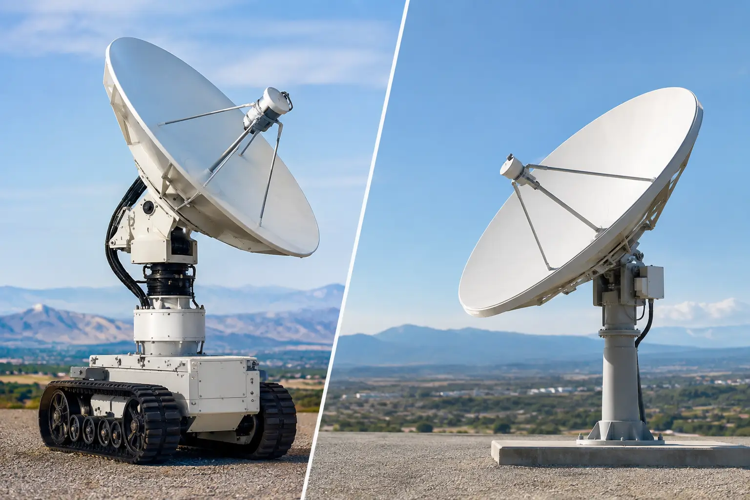
Stabilized, auto-aiming antenna systems address a central weakness of fixed directional antennas on moving platforms: the antenna must stay aligned while both the vessel and the RF path change. Tracking systems that combine position data, heading, attitude information, and path calculation can maintain a directional connection with far more consistency than manual aiming. The payoff is not only higher throughput. It is reduced link reacquisition time and fewer avoidable operational interruptions.
Choose Backhaul by Operating Zone
No single transport is ideal across all operating areas. Cellular can be cost-effective in coastal coverage areas but can become congested or unavailable beyond shore. Satellite offers broad reach but may introduce higher latency, capacity constraints, and recurring service costs. Microwave can provide high capacity and low latency where a shore site, platform, or relay network is available, but it depends on engineered line of sight and accurate pointing.
A resilient architecture usually uses more than one path. The primary link should support normal operational demand, while a secondary path preserves essential functions when conditions change. This does not mean every application should fail over in the same way. Bridge communications, alarms, and command traffic should retain priority. Bulk file transfer, passenger or crew traffic, and noncritical updates can slow down, wait, or move to a lower-cost transport.
Build the Onboard Network Around Traffic Priority
Once backhaul reaches the vessel, the onboard network must prevent lower-value traffic from consuming the connection. Without segmentation and quality-of-service policy, a software update or recreational video stream can compete directly with operations traffic at the exact moment a constrained backhaul link is needed.
Separate operational technology, business systems, crew or guest access, and management traffic into defined network segments. Use VLANs, access controls, and firewall policy to limit unnecessary traffic movement between those segments. This improves performance, but it also narrows the exposure created when personal devices, contractor equipment, or temporary systems connect onboard.
Quality of service should be designed around application behavior rather than broad labels alone. Voice needs predictable latency and low jitter. Real-time video may require controlled bandwidth and packet-loss protection. Remote monitoring often uses little bandwidth but may need high availability. Large transfers can tolerate delay and should be rate-limited or scheduled for periods when capacity is available.
The same principle applies to Wi-Fi. Coverage planning inside metal compartments, below decks, and around machinery spaces is different from an office deployment. Bulkheads, watertight doors, equipment noise, reflective surfaces, and changing cargo layouts all affect propagation. A site survey should identify where devices actually operate, not just where access points are convenient to mount. In many cases, more access points at lower transmit power provide better roaming behavior and less co-channel interference than a few high-power radios.
Engineer Antenna Placement, Not Just Antenna Selection
A high-gain antenna cannot compensate for poor placement. Mounting height, obstructions, cable runs, vibration, corrosion exposure, and separation from other RF systems all influence real-world performance. The best location for a tracking antenna may differ from the most accessible location, which is why mechanical, electrical, and RF considerations need to be coordinated early.
Keep RF feeder runs as short as practical, because cable loss becomes more consequential at higher frequencies. Where long runs cannot be avoided, place radio equipment closer to the antenna or specify the appropriate low-loss components. Equipment enclosures, connectors, grounding, surge protection, and weatherproofing should be selected for the marine environment rather than treated as installation details.
Co-site interference is another common issue. Marine assets can carry radar, VHF, AIS, cellular equipment, satellite terminals, Wi-Fi, telemetry radios, and other transmitters in close proximity. Frequency planning, antenna spacing, filtering, shielding, and transmit-power control may be required to protect receiver performance. An intermittent interference issue can look like a backhaul failure unless the network team has visibility into RF conditions.
Make Failover Deliberate and Test It Under Motion
A secondary link has limited value if failover only works in a dockside test. The system should be validated while the asset is moving, turning, and operating in the conditions that challenge the primary path. Measure detection time, route convergence, application recovery, and the behavior of critical sessions after a handoff. Some applications reconnect quickly; others require specific session persistence or routing controls.
Use health checks that measure more than whether an interface is up. A cellular modem may show a connection while providing unusable throughput. A microwave link may remain associated while packet loss rises beyond the threshold for voice or control traffic. Monitor latency, jitter, packet loss, available bandwidth, signal metrics, and error rates so the system can make informed decisions about when to switch paths.
Capacity policies matter during failover. If a vessel moves from a high-capacity microwave path to a limited satellite or cellular link, the network should immediately enforce the appropriate traffic rules. Automatic policy changes can protect mission traffic before users notice the connection has changed.
Design for Operations, Support, and Lifecycle Cost
Onboard connectivity is an operational system, not a one-time hardware purchase. Remote management, configuration backup, event logging, and performance monitoring should be included in the architecture from the beginning. A support team needs enough visibility to distinguish an RF alignment issue from a carrier outage, onboard interference event, switch failure, or application problem.
Standardizing equipment and interfaces across a fleet can reduce training burden and speed repairs, but standardization should not force identical designs across unlike vessels. A harbor tug, an offshore construction vessel, and a patrol boat may need different antennas, link types, and traffic policies. The better approach is a common operational framework with vessel-specific RF engineering.
BATS Wireless approaches these deployments as integrated communications systems, combining stabilized microwave, auto-aiming tracking capability, compatible radios, onboard networking, and technical services around the actual operating environment. That integration matters when antenna behavior, backhaul availability, and onboard traffic policy must work together under motion.
The most useful next step is to capture real operational data before specifying equipment: routes, speeds, headings, vessel geometry, current outage patterns, application priorities, and reachable shore or offshore endpoints. Those details turn a generic connectivity request into an engineered design that can keep working when the vessel is far from an easy fix.

October 5, 2026
October 5, 2026

October 5, 2026

October 5, 2026
