
Remote Site Spectrum Planning That Holds Up
Remote site spectrum planning aligns coverage, capacity, backhaul, and interference controls so mission-critical networks perform reliably in the field.


A remote network rarely fails because someone forgot to install a radio. It fails because the RF plan was treated as a channel assignment exercise instead of an operational design decision. Remote site spectrum planning determines whether a drilling pad, vessel, wind farm, incident command post, or temporary construction site receives predictable service when terrain, weather, movement, and distance begin working against the network.
For mission-critical operations, spectrum is not an abstract regulatory concern. It is the finite resource that carries voice, telemetry, video, dispatch, private LTE or 5G traffic, and backhaul between the field and the enterprise. A workable plan must account for the RF environment, licensed and shared-use options, antenna placement, propagation, interference, capacity demand, and the transport path that carries traffic beyond the site.
Start Remote Site Spectrum Planning With the Mission
The first question is not which band is available. It is what communications must continue when conditions degrade. A site supporting basic sensors and low-rate SCADA has a very different spectrum requirement than a mobile command unit sending multiple HD video feeds, voice traffic, mapping data, and device telemetry at the same time.
Define the applications by their operational consequence. Identify which traffic needs low latency, which can tolerate delay, which requires high upstream capacity, and which must remain available during a backhaul interruption. This establishes the traffic profile before frequency, radio, and antenna decisions narrow the design.
Coverage targets also need to be specific. “Cover the site” is not an engineering requirement. The boundary may include a production area, access road, laydown yard, offshore platform deck, perimeter, nearby staging area, or moving vehicle route. Each area can have a different propagation condition and service expectation.
A sound planning baseline documents expected users, connected devices, peak traffic, uplink and downlink ratios, availability targets, expansion assumptions, and the duration of deployment. Temporary sites still need this discipline. A network planned for a 30-day response operation can become a six-month deployment with more users, more cameras, and far more RF congestion than originally expected.
Evaluate the Spectrum Environment Before Selecting Equipment
Band selection begins with what is legally available and operationally practical at the location. The right option may be licensed spectrum, a shared-access model, unlicensed spectrum, or a combination of bands that separates access, mobility, and backhaul functions.
Licensed spectrum can provide stronger interference control and more predictable service, but it may involve acquisition cost, coordination, and geographic restrictions. Shared spectrum can be an effective option for private LTE and 5G deployments where availability, device support, and authorization conditions align with the use case. Unlicensed spectrum can reduce deployment cost and speed installation, but it requires disciplined channel planning and a realistic assessment of competing RF activity.
A spectrum survey should not stop at a single scan near the equipment shelter. Measure at likely tower locations, operational work areas, vessel deck positions, elevated terrain, and edges of the intended coverage zone. Record activity across different times of day when possible. Interference may come from neighboring industrial operations, Wi-Fi systems, point-to-point links, radar activity, consumer devices, or equipment that appears only during a particular work cycle.
The survey should also distinguish between a clean-looking band and a usable channel. Wideband noise, intermittent transmissions, adjacent-channel energy, and receiver desensitization can all reduce performance even when a basic spectrum display appears acceptable.
Plan Access and Backhaul as Separate RF Problems
Field access and backhaul are often forced into the same frequency conversation, even though they have different jobs. The access network must support devices across a broad and changing service area. The backhaul path must deliver sustained capacity between fixed or moving endpoints, often over a much longer distance.
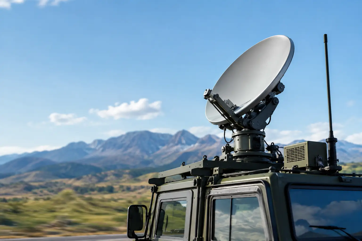
For a fixed remote site, a high-capacity microwave path may be the most efficient backhaul choice when line of sight and path clearance are available. For a vessel, vehicle, or mobile command platform, stabilized and auto-aiming antennas can preserve a directional connection while the platform moves, pitches, rolls, or changes heading. In these cases, antenna tracking performance is part of spectrum performance. A clean channel provides little value if the link cannot stay pointed accurately enough to maintain fade margin.
Keeping access and backhaul on distinct bands where practical simplifies interference management and protects user service from backhaul-related contention. It also gives the engineering team more flexibility to adjust one layer without disrupting the other.
Model Propagation, Not Just Distance
Distance alone is a poor predictor of remote wireless performance. A 10-mile path across open water may be more achievable than a one-mile path through dense foliage, steel structures, uneven terrain, or heavy industrial equipment. The frequency band matters because propagation, penetration, available bandwidth, antenna size, and achievable throughput change considerably from one band to another.
Terrain and clutter modeling should incorporate elevation, vegetation, buildings, cranes, tanks, machinery, and future construction where relevant. For point-to-point and point-to-multipoint systems, calculate Fresnel zone clearance rather than relying on visual line of sight. A visible path with obstructed Fresnel clearance can produce unstable throughput, modulation changes, and weather-sensitive outages.
Weather deserves the same attention. Rain attenuation can materially affect higher-frequency microwave links, particularly where high availability is required. Offshore and coastal systems must also account for salt exposure, high winds, sea clutter, and multipath reflections from water. In oil and gas, metal infrastructure and changing equipment positions can alter RF behavior after installation.
The engineering objective is not maximum laboratory throughput. It is sufficient throughput with margin. Link budgets should include transmitter power, antenna gain, cable and connector loss, receiver sensitivity, modulation targets, fade margin, and realistic environmental loss. A design that only works at its highest modulation rate under ideal conditions is not a field-ready design.
Design for Interference Control and Capacity Growth
Interference management is most effective when handled during architecture design rather than after users report poor service. Channel reuse, sector orientation, antenna beamwidth, polarization, transmit power, and physical separation all influence how systems coexist.
Higher power is not automatically a cure. Increasing power can expand coverage, but it can also raise the interference floor, overload nearby receivers, and create a weaker signal-to-interference ratio for the entire network. Directional antennas, careful downtilt, sectorization, and appropriate channel width often deliver a better result than simply increasing transmit power.
Channel width is another trade-off. Wider channels can support greater peak throughput but consume more spectrum and may be more exposed to interference. Narrower channels can improve reuse and resilience in congested environments, though they limit capacity. The correct choice depends on traffic demand, available spectrum, radio capabilities, and the degree of control over the surrounding RF environment.
For private LTE and 5G, capacity planning must account for more than subscriber count. Camera uplinks, body-worn video, autonomous equipment, industrial sensors, push-to-talk services, and software updates can create very different loading patterns. Design around busy-hour demand and critical-event demand, not average utilization. The worst period is usually when the network is most needed.
Treat Antenna Engineering as a Core Design Variable
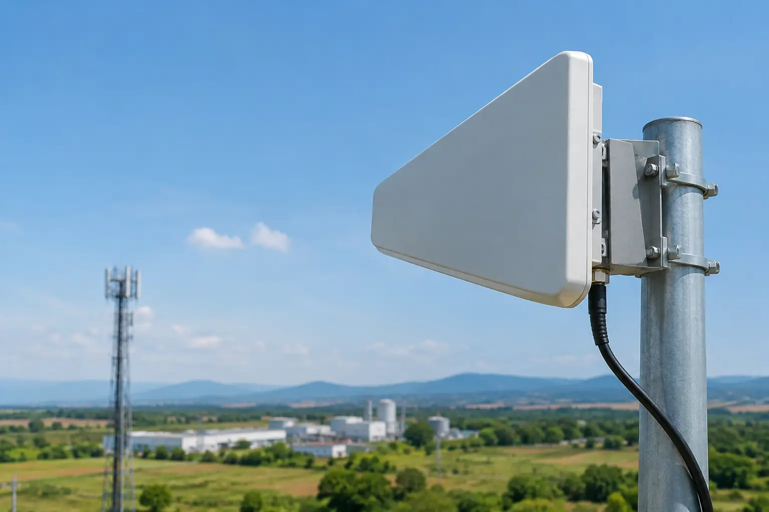
A spectrum plan can be technically correct and still fail because the antenna system was selected or installed without enough rigor. Antenna gain, beam pattern, polarization, mounting height, cable routing, radome selection, grounding, and structural stability directly affect RF outcomes.
At fixed sites, height can improve line of sight and clearance, but excessive height may introduce wind loading, permitting issues, longer cable runs, or unwanted interference exposure. At mobile and maritime sites, stabilization and tracking become central to maintaining link integrity. The antenna must compensate for platform movement quickly enough to preserve the path without creating avoidable handoffs or throughput drops.
Integrated radio and antenna compatibility also matters. Connector loss, supported frequency ranges, radio output limits, MIMO configuration, and environmental ratings should be verified as a system. Field deployments often combine equipment from multiple manufacturers, and a mismatch that looks minor on a datasheet can become a costly site visit.
BATS Wireless approaches these deployments as complete RF and transport systems, combining path calculation, auto-aiming antenna capability, stabilized microwave systems, integrated radios, and technical support for demanding operational environments.
Validate in the Field and Keep Measuring
No propagation model fully captures a live remote site. Commissioning should include signal and quality measurements across the intended service area, throughput testing under load, latency and packet-loss checks, backhaul validation, and failover testing. Test from actual user locations, not only from convenient points near the network enclosure.
Establish baseline metrics before turnover. Record received signal levels, signal-to-interference-plus-noise ratio, modulation rates, channel utilization, throughput, latency, packet loss, and link availability. These measurements help distinguish a new environmental issue from a configuration or equipment fault later.
Remote sites change. A new crane, parked vessel, growing tree line, added camera system, adjacent contractor network, or revised work boundary can alter the RF plan. Review spectrum use when operations expand, traffic patterns shift, or performance indicators begin trending downward. The goal is not to rebuild the network at every change, but to keep the design aligned with the mission it supports.
The strongest remote wireless systems are planned with enough margin to absorb real conditions, enough visibility to identify degradation early, and enough engineering flexibility to adapt without interrupting operations.

October 22, 2026

October 22, 2026
October 22, 2026
October 22, 2026
