
Stabilized Antenna Platforms for Moving Networks
Stabilized antenna platforms keep mobile crews, vessels, and remote assets connected by holding precise RF links through motion, weather, and distance.

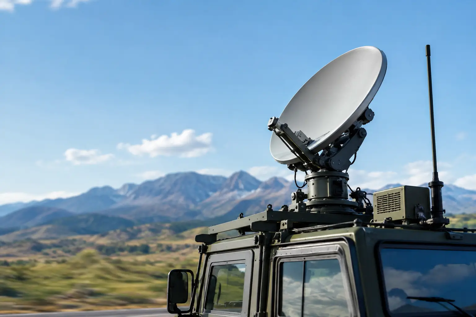
A microwave link can have clear line of sight, sufficient transmit power, and a properly engineered path, yet still fail when the platform moves. On a vessel, vehicle, aircraft support asset, or temporary industrial installation, small changes in heading, pitch, roll, vibration, or elevation can push a narrow RF beam off target. Stabilized antenna platforms address that problem by continuously maintaining antenna alignment while the asset and operating environment change around them.
For organizations that depend on field communications, this is not a cosmetic improvement to antenna hardware. It is the difference between a link that works during commissioning and a network that remains available during operations. A stabilized system can preserve high-capacity backhaul, extend private LTE or 5G coverage, support onboard users, and keep command-and-control traffic moving when fixed infrastructure is unavailable or impractical.
Why Motion Changes the RF Design
At lower frequencies and with wide beamwidth antennas, an installation can tolerate more movement before signal loss becomes operationally significant. That tolerance declines as frequency rises, antenna gain increases, and beamwidth narrows. Microwave and millimeter-wave links deliver valuable capacity, but they demand more precise pointing than broad-area radio systems.
A vessel turning through a sea state may experience yaw, pitch, and roll at the same time. A ground vehicle traveling over uneven terrain introduces rapid vibration and orientation changes. Even a stationary-looking platform, such as a wind turbine service vessel or floating industrial asset, can move enough to degrade a point-to-point link. The result may be reduced modulation, increased packet loss, repeated link renegotiation, or a complete outage.
The engineering challenge is not simply to make an antenna move. The system must determine where the remote endpoint is, understand the local platform orientation, calculate the required pointing angle, and command the antenna quickly and accurately enough to keep the RF path within its usable alignment window.
How Stabilized Antenna Platforms Maintain the Link
A stabilized antenna platform combines mechanical positioning, sensors, control software, and radio integration. The implementation varies by application, but the operating principle is consistent: measure motion, calculate the intended antenna position, and correct alignment in real time.
Sensors and Position Awareness
The platform generally relies on a combination of GNSS position data, compass or heading data, inertial measurement units, gyroscopes, and accelerometers. These inputs establish the asset’s location, heading, angular movement, and attitude. When the remote site’s coordinates are known, the control system can calculate azimuth and elevation continuously.
Sensor quality matters. A consumer-grade heading source may be adequate for a broad beam application, while high-gain microwave operation requires more accurate and stable reference data. Magnetic interference, GNSS availability, vibration, and installation location can all affect sensor performance. The antenna system should be engineered with these conditions in mind rather than treating position data as a generic input.
Auto-Aiming and Closed-Loop Correction
Initial pointing based on coordinates is only the first step. Practical systems also benefit from closed-loop correction using received signal strength, signal quality measurements, or radio feedback. This allows the antenna to refine its position after acquisition and compensate for small errors in survey data, sensor readings, mechanical offsets, or remote-site coordinates.
Auto-aiming reduces the burden on field personnel. Instead of manually searching for a distant endpoint, operators can deploy an antenna system that calculates the target position, acquires the link, and maintains alignment as conditions change. That capability is particularly valuable for emergency response, temporary network extensions, maritime operations, and mobile command assets where experienced RF technicians may not be present at every operating location.
Mechanical Stability and Environmental Design
Control logic cannot overcome a poorly matched mechanical assembly. The mount, motors, bearings, radome, cable routing, and enclosure must withstand expected loads while maintaining pointing accuracy. Wind loading is especially relevant for exposed installations. A larger antenna may improve link budget, but it also increases surface area and torque requirements.
There is always a trade-off between antenna gain, stabilization precision, platform size, power consumption, and environmental survivability. The best design is not automatically the largest dish or the fastest pan-tilt unit. It is the system sized for the required availability, range, capacity, and operating conditions.
Where Stabilized Antenna Platforms Deliver Value
Maritime networks are among the clearest use cases. Workboats, ferries, offshore support vessels, aquaculture operations, and port assets often need reliable broadband beyond the reach of shore-based Wi-Fi or cellular service. A stabilized microwave system can maintain a high-capacity connection to shore or between operating assets while supporting onboard business applications, crew connectivity, video, sensors, and private cellular coverage.
Defense and public safety operations face a different but equally demanding requirement: deployable connectivity with minimal setup time. Mobile command vehicles, tactical communications assets, and incident response teams may need to establish backhaul from locations where terrestrial service is congested, damaged, or nonexistent. Auto-aiming antennas reduce setup complexity and help teams sustain a directional link while vehicles reposition or operate on uneven ground.
Industrial operators use stabilized links when fixed fiber is uneconomical, slow to deploy, or vulnerable to damage. Oil and gas sites, construction projects, mining operations, wind farms, and temporary logistics hubs may require broadband for operational technology, cameras, worker communications, telemetry, and access to centralized systems. In these environments, a directional wireless path can be a cost-saving solution, provided the antenna system can maintain alignment through movement and environmental stress.
Ground-to-air communications also require disciplined tracking and path design. Aircraft are fast-moving endpoints with changing altitude, range, and bearing. The antenna platform must calculate target movement quickly, sustain acquisition, and integrate with the selected radio architecture. The same principle applies to any use case where a remote node is mobile and the wireless link cannot tolerate long interruptions.
Engineering the Platform as Part of the Network
A stabilized antenna should not be selected as an isolated product. Its performance depends on the complete network architecture, including frequency selection, available spectrum, radio compatibility, path profile, antenna gain, cable loss, power source, network security, and traffic priorities.
For example, a long-range microwave link may require licensed spectrum, high-gain antennas, and a carefully modeled fade margin to meet availability targets. A shorter temporary connection may favor a more portable unlicensed configuration with lower cost and faster deployment. Neither approach is universally better. The correct choice depends on throughput requirements, interference conditions, regulatory constraints, expected uptime, and the consequence of an outage.
Radio integration is equally important. The antenna positioner, modem or radio, network switch, cellular core components, and onboard distribution network must operate as a coordinated system. A deployment that treats these elements as separate purchases can create avoidable compatibility issues, difficult troubleshooting, and unclear support responsibility.
BATS Wireless approaches these deployments as engineered communications systems, combining antenna tracking capability, stabilized microwave technology, integrated radios, and network design around the actual operating environment. That approach matters when the network must perform beyond a lab test or a fixed-site demonstration.
Key Questions Before Deployment
Before specifying a stabilized platform, decision-makers should define the operational requirement in measurable terms. Start with the remote endpoint: Is it fixed, moving predictably, or moving unpredictably? Determine the maximum range, expected platform motion, antenna elevation constraints, and the time allowed to establish a connection.
Next, define service expectations. A link carrying best-effort crew internet has a different availability requirement than one carrying dispatch, surveillance video, SCADA traffic, or emergency communications. The traffic profile should influence bandwidth targets, redundancy design, quality-of-service policies, and whether an alternate path such as cellular, satellite, or a second microwave route is required.
Environmental details are not secondary. Salt exposure, ice, dust, shock, vibration, temperature range, wind speed, and maintenance access all influence equipment selection. So does installation geometry. An antenna mounted near exhaust stacks, radar, cranes, masts, or reflective metal structures may encounter interference, blockage, or multipath that does not appear on an early site plan.
Finally, plan for operations after commissioning. Teams need a way to monitor link quality, receive alarms, verify antenna status, manage software versions, and troubleshoot remotely. A capable stabilization platform provides value only when operators can see whether a problem is caused by RF conditions, sensor input, mechanical movement, radio configuration, or the upstream network.
Reliability Comes From the Full System
Stabilization improves link continuity, but it does not eliminate the fundamentals of wireless engineering. Clear path design, adequate fade margin, correct frequency planning, sound grounding, weather protection, and disciplined installation remain essential. A platform that points perfectly at an obstructed or poorly designed path will still produce poor results.
The strongest deployments pair precision tracking with realistic network design and field support. When the antenna, radio, power system, and network architecture are selected for the mission rather than for a catalog specification, mobile and remote assets can operate with the broadband capacity their teams actually need. Start by defining what connectivity failure costs the operation, then engineer the stabilized link around that standard.

October 22, 2026

October 22, 2026
October 22, 2026

October 22, 2026
