
A Drone Communications Example for Field Networks
See a drone communications example built for reliable command, payload data, backhaul, and onboard network performance during demanding field operations.

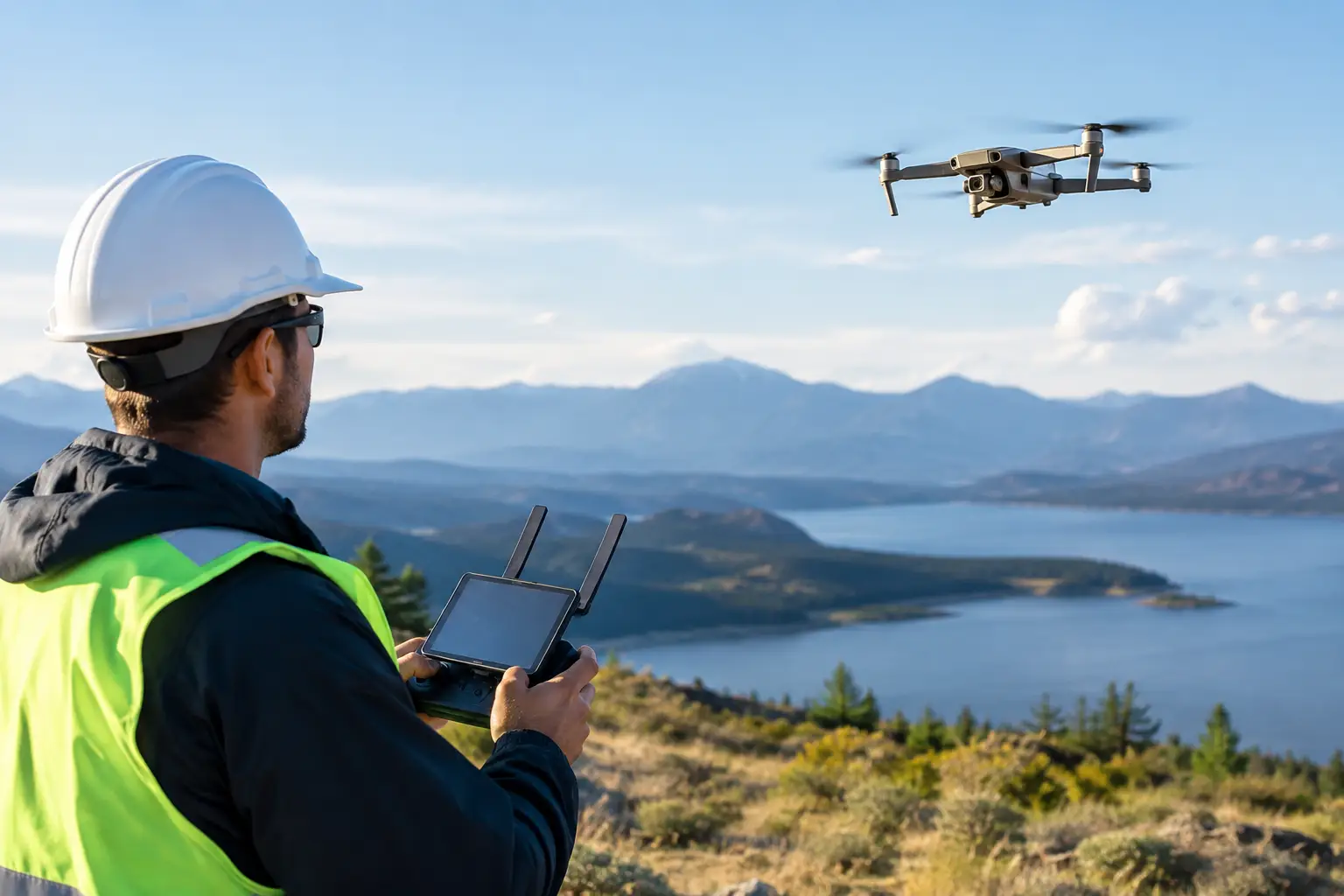
A multirotor inspecting a transmission corridor can be airborne in minutes, but the mission fails if the pilot loses command authority beyond the first ridge or the video feed degrades when it matters most. A practical drone communications example is therefore not just a radio link between an operator and an aircraft. It is an engineered system that separates critical control traffic from high-bandwidth payload data, accounts for aircraft movement, and provides a dependable path back to the operations center.
For industrial, public safety, defense, and utility users, the communications design determines how far a drone can operate, what data it can carry, and whether the aircraft remains a useful field asset when terrain, weather, distance, or RF congestion work against it.
A Drone Communications Example for Extended Operations
Consider a utility conducting beyond-visual-line-of-sight inspection along a remote pipeline or power corridor. The aircraft carries an electro-optical camera, a thermal sensor, a flight controller, and an onboard network. A field team launches from a mobile command vehicle, while engineering personnel at a regional operations center need access to selected video and telemetry.
The communications architecture has four distinct traffic types: command and control, aircraft telemetry, mission payload data, and operational backhaul. Each has different latency, bandwidth, and availability requirements. Treating them as one undifferentiated connection is a common design mistake.
Command and control traffic is low bandwidth but mission critical. It must maintain predictable latency and should have a protected primary path and a defined fallback path. Telemetry – position, altitude, battery status, link quality, and flight health – is also low bandwidth, yet it must remain visible to the operator and any authorized supervisory system.
Payload traffic is different. A 4K video stream, thermal imagery, LiDAR data, or multispectral collection can require substantially more capacity. Payload quality may be adaptive during a constrained-link event, while command traffic should retain priority. The network must enforce that distinction rather than hoping the radio scheduler handles it appropriately.
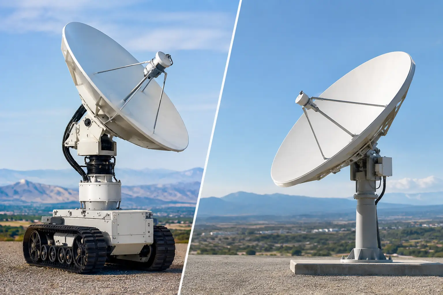
In this example, the command vehicle establishes a private 4G/5G coverage area around the launch site and uses a stabilized, auto-aiming microwave system for long-range backhaul to a fixed network point. The drone’s onboard router connects flight systems and payload equipment on segregated network segments. As the aircraft moves beyond the local coverage cell, a purpose-designed air-to-ground link carries command, telemetry, and selected video to a tracking antenna at the vehicle.
The tracking system continuously calculates the aircraft position and directs the antenna toward the moving endpoint. This matters because a conventional fixed directional antenna delivers gain only while the aircraft remains within its narrow beamwidth. Auto-aiming capability maintains the high-gain path as heading, altitude, and range change.
Why the Architecture Uses More Than One Link
A drone can use cellular, unlicensed RF, licensed spectrum, microwave, satellite, or a combination of these technologies. The right answer depends on the operating area, mission profile, regulatory requirements, spectrum availability, and the consequence of a lost link.
In the utility scenario, private LTE or 5G may provide strong near-field connectivity around the command vehicle, staging yard, or substation. It can support crew tablets, vehicle systems, cameras, and the aircraft when it is within coverage. However, cellular alone may not provide continuous service along a remote route. Public carrier coverage can be inconsistent, overloaded during an incident, or unavailable in terrain shadow.
A dedicated air-to-ground RF link can extend controlled coverage along the flight path. Where high-throughput video must reach a distant operations center, stabilized microwave backhaul gives the command vehicle a high-capacity connection without relying on a temporary wired circuit. Satellite can provide another backhaul option in isolated locations, though its latency, capacity, cost, and terminal constraints need to be evaluated against the mission.
Redundancy is not simply adding a second radio. The alternate path must be independent enough to survive the likely failure mode. For example, two links that depend on the same tower, power source, or obstructed line of sight may not create meaningful resilience. The system should also define what happens when video is lost, when payload throughput falls below threshold, or when command connectivity degrades.
Engineering the Air-to-Ground Segment
The air-to-ground segment is where network planning becomes aircraft planning. Link budget, antenna gain, aircraft dynamics, operating altitude, Fresnel-zone clearance, terrain masking, and RF interference all affect actual performance.
A directional ground antenna increases range and throughput by concentrating RF energy toward the aircraft. The trade-off is that it must stay aligned. A manually aimed antenna may be acceptable for short, slow, line-of-sight flights. It is not a dependable choice for long-range routes, maneuvering aircraft, maritime platforms, or missions where one operator cannot continuously manage antenna pointing.
An auto-tracking antenna system receives position information from the aircraft and uses that data to calculate azimuth and elevation. Stabilization becomes especially important when the ground station is mounted on a moving vehicle, vessel, or trailer subjected to wind and vibration. The objective is not just to acquire the aircraft at launch. It is to maintain sufficient signal margin through turns, changing elevations, and varying ranges.
The aircraft installation also requires careful RF integration. Antenna placement must minimize shadowing from airframe components, payload gimbals, batteries, and other radios. Cable losses, connector quality, electromagnetic compatibility, and available aircraft power all matter. A high-performance ground system cannot compensate for an onboard installation that blocks the antenna during normal flight attitudes.
Onboard Networks Keep Mission Systems Manageable
A drone carrying multiple sensors should not operate as a collection of disconnected devices. An onboard network provides a structured way to connect payloads, flight-adjacent systems, radios, edge compute equipment, and storage.
Network segmentation is useful when a video encoder, mission computer, and flight-control interface share the aircraft. Separate virtual LANs or physically separate interfaces can prevent a high-bandwidth payload stream from affecting critical control-related traffic. Quality-of-service policies should reserve capacity for command and telemetry before payload traffic consumes available throughput.
This approach also supports flexible payload changes. A public safety aircraft may carry a visible-light camera for one mission and a thermal sensor, mesh node, or environmental instrument for another. A properly designed onboard network lets operators integrate equipment without rebuilding the communications architecture each time.
Security belongs in the same design discussion. Authentication, encrypted traffic, controlled management access, and defined interfaces to enterprise or government networks reduce exposure. The level of protection should match the mission and data sensitivity, but security controls cannot be added carelessly if they create latency, processing, or operational burdens that field teams cannot sustain.
Planning for Range Is Not Enough
A stated radio range is only one input. The operational question is whether the system will deliver required availability across the full route and under expected conditions. A 20-mile link over open water has different constraints than a 20-mile link through rolling terrain, industrial clutter, forest canopy, or an urban incident scene.
Path analysis should identify line-of-sight limits, terrain obstructions, expected Fresnel-zone intrusions, candidate relay points, and areas where an aircraft may need to change altitude or use a different communications mode. It should also account for weather exposure, equipment mounting, generator or battery autonomy, and setup time. A system that performs well in an RF test but requires hours of alignment and site preparation may not fit a rapid-response mission.
For some deployments, the most cost-effective design uses a mobile tracking station at the edge of the work area and a high-capacity backhaul link to operations. For others, fixed nodes, relay sites, or private cellular infrastructure are justified because the route is flown repeatedly. There is no universal drone network architecture. The right design follows the mission, not a catalog specification.
Operational Checks Before Launch
Communications readiness should be verified as part of the flight workflow, not treated as an IT task completed weeks earlier. Teams should confirm the primary and backup command paths, antenna tracking status, signal margin, payload-stream performance, network segmentation, and backhaul availability before the aircraft leaves the launch area.
They also need clear decision points. If payload video drops to an unusable quality level, does the aircraft continue collecting locally, return to a stronger coverage area, or terminate the mission? If the primary backhaul fails but local command remains available, who can view the data and where is it recorded? These decisions should be documented and exercised before a live incident or critical inspection.
BATS Wireless designs communications systems around these field realities: moving endpoints, high-value data, constrained spectrum, and the need to keep operations connected beyond conventional broadband coverage.
A useful next step is to map one real flight route, one payload set, and one failure scenario in detail. That exercise quickly reveals whether the drone link is merely functional at launch or engineered to support the mission all the way through recovery.

October 10, 2026

October 10, 2026

October 10, 2026
October 10, 2026
