
Energy Site Wireless Deployment Example That Works
See an energy site wireless deployment example built for remote operations, with private LTE, microwave backhaul, redundancy, and field-ready design.


A productive energy site can lose operational visibility long before it loses power. A compressor station, drilling pad, wind facility, or remote substation may have local controls, but without dependable connectivity, SCADA data arrives late, video cannot be reviewed, crews rely on voice calls, and remote specialists cannot support the field. This energy site wireless deployment example shows how an engineered private wireless network can extend broadband across a geographically dispersed operation without treating every location as an isolated networking project.
The scenario is a remote oil and gas production field with a central operations facility, six well pads, a compressor station, two tank batteries, and mobile maintenance crews. The site spans approximately 18 miles of rolling terrain. Fiber is available at the central facility but not at the field assets. Cellular coverage exists in places, but it is inconsistent and cannot support the operational control, security, and uptime requirements of the operator.
The operational requirement
The operator needs more than internet access at a few remote cabinets. It needs a communications architecture that carries SCADA traffic, IP video, voice communications, field tablets, environmental monitoring, access control, and limited corporate data. Traffic types have different tolerance for delay, packet loss, and interruption. A video stream can adapt to reduced bandwidth; control telemetry and alarm traffic need predictable delivery; a voice call needs low latency; and remote engineering access must be segmented and secured.
The design target is coverage and backhaul availability that supports 24/7 operations, with local survivability if a primary path fails. The system also needs to accommodate future expansion. A new pad or temporary work area should not require a full redesign of the network core.
This is where commodity Wi-Fi and unmanaged cellular routers commonly fall short. They can be useful at the edge, but they do not solve long-distance transport, RF planning, path obstruction, network segmentation, power resilience, or mobility across the full site.
The energy site wireless deployment example
At the central operations facility, fiber terminates in a secure network room that houses the routing, firewall, private LTE core functions, monitoring platform, and power protection. This is the network’s aggregation point. From there, licensed or coordinated microwave links provide high-capacity transport to two elevated relay locations selected through path surveys and terrain analysis.
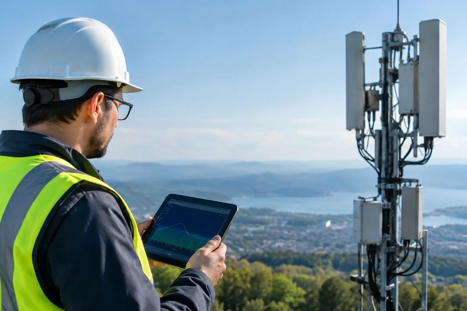
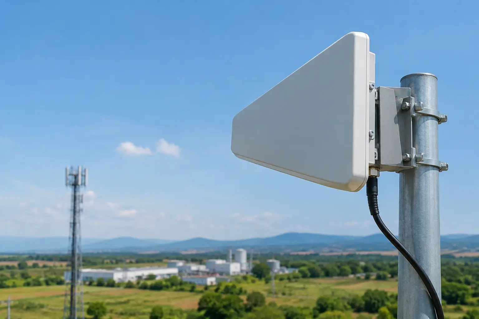
The first relay covers the western well pads and compressor station. The second relay covers the eastern pads and tank batteries. Each relay uses tower-mounted microwave equipment with protected power, surge suppression, and environmental enclosures. The relays are positioned not simply for distance, but for usable line of sight, Fresnel-zone clearance, maintainable access, and an upgrade path for additional sectors or radios.
From these relay points, a private LTE network provides area coverage to fixed and mobile assets. LTE sectors serve vehicle-mounted routers, rugged field tablets, cameras, sensors, and equipment controllers fitted with compatible user equipment. In higher-density areas, such as the compressor station, localized Wi-Fi can supplement LTE for inside-building access and high-bandwidth maintenance tasks. The key distinction is that Wi-Fi is not asked to carry traffic across miles of uneven terrain.
Why microwave backhaul is central to the design
Private LTE or 5G coverage is only as useful as the transport behind it. In this deployment, microwave creates the backbone between the fiber-fed operations center and remote radio locations. It delivers predictable capacity without the recurring cost and service uncertainty of relying on public carrier networks at every asset.
Link engineering matters. A path that looks clear from a mapping tool may be degraded by tree growth, seasonal foliage, tower movement, nearby structures, or a partially blocked Fresnel zone. A proper design evaluates path length, elevation, antenna size, spectrum availability, fade margin, rainfall exposure, expected throughput, and the need for protected routing.
For the two most critical locations, the microwave network is configured with alternate paths. If the direct path from the operations facility to the western relay becomes unavailable, traffic can reroute through the eastern relay and a cross-field link. This does not eliminate every failure mode, but it prevents a single tower, radio, or path event from isolating an entire production area.
Private LTE for controlled site mobility
The private LTE layer gives the operator ownership of coverage, quality-of-service policies, device access, and traffic segmentation. A maintenance truck moving between pads stays connected to the same managed wireless environment instead of shifting between weak public cellular signals or attempting to join separate local networks.
The network assigns priority based on operational need. SCADA, alarms, dispatch voice, and critical control-related traffic receive higher priority than nonessential user traffic. Camera streams can be rate-limited or configured for event-based recording. Contractor devices can be placed on a separate network segment with restricted access to operational systems.
This architecture is particularly valuable where crews work near rotating equipment, storage tanks, pipeline infrastructure, or other areas where hands-free communications and live situational awareness matter. It also gives the operator a practical foundation for connected-worker applications, inspection workflows, and condition-monitoring devices.
Designing for harsh field conditions
An energy site deployment succeeds or fails in the field, not in a coverage prediction file. Equipment must be selected and installed for heat, cold, vibration, wind loading, dust, moisture, lightning exposure, and limited maintenance access. That includes the radios, antennas, mounts, cabling, power systems, grounding, enclosures, and network cabinets.
At the relay sites, the design uses hardened outdoor radios, appropriately rated antennas, bonded and grounded structures, and DC power systems supported by battery backup. Where commercial power is not dependable, solar and generator-supported options may be evaluated. The right choice depends on load requirements, site access, solar conditions, fuel logistics, and the required outage duration.
Antenna placement deserves close attention. Mounting an antenna higher may improve coverage, but it can increase tower loading, complicate maintenance, and expose the installation to greater wind and lightning risk. At some locations, a lower site with a clearer path and simpler service access is the better engineering decision.
What the network carries at each location
The central facility receives operational telemetry from PLCs and RTUs at every remote asset. Video from gate cameras, tank batteries, and equipment perimeters is available to authorized operations and security personnel. Mobile crews use connected tablets for work orders, documentation, and video support calls with subject-matter experts.
At the compressor station, the network supports monitoring systems, access control, fixed cameras, and maintenance connectivity. At well pads, the traffic profile is lighter but still operationally important: telemetry, alarm reporting, periodic video, environmental sensors, and technician access. This difference in traffic demand is why the radio, antenna, and backhaul design should be site-specific rather than copied identically across every location.
The architecture also supports temporary assets. A drilling campaign, turnaround project, or pipeline repair operation can receive a rapidly deployed LTE sector, point-to-point microwave link, or vehicle-based communications package that joins the existing network under the same security and monitoring policies.
Where auto-aiming and stabilized systems fit
Fixed towers solve much of the field, but some energy operations include moving assets or temporary locations where static antennas are impractical. Mobile command trailers, vessels supporting offshore energy work, inspection vehicles, and rapid-response teams may need broadband while moving or while operating from sites without established infrastructure.
In those cases, auto-aiming antenna systems and stabilized microwave platforms can maintain a directional link to a known network point. The benefit is not merely convenience. Directional antennas can provide longer range and more controlled RF performance than an omnidirectional approach, provided the system can maintain alignment as the platform moves or shifts.
BATS Wireless designs these systems around the actual operating environment, including movement profile, antenna placement, path calculation, radio compatibility, available towers or hubs, and application bandwidth. A tracked link is not the answer for every use case. For a small, stationary sensor site, a fixed radio may be simpler and more cost-effective. For a mobile operation that requires high-throughput backhaul beyond cellular coverage, tracking capability can be operationally decisive.
The trade-offs that determine the final design
There is no single best spectrum band, topology, or radio type for every energy site. Lower-frequency private LTE can offer broader coverage and better propagation through some obstructions, while higher bands may provide more capacity in localized areas. Licensed microwave can offer stronger interference control, while unlicensed options may be appropriate for shorter, less critical paths where spectrum conditions are favorable.
Redundancy also has a cost. Dual backhaul paths, spare radios, extended battery runtime, and diverse tower routes improve availability, but not every remote pad needs the same protection level as a central compressor station. Criticality analysis should drive investment. A practical design classifies sites by operational impact and applies resilience where an outage would create material safety, production, environmental, or security risk.
Cybersecurity must be designed into the network as well. Private wireless does not mean automatically secure wireless. The operator still needs device authentication, encrypted traffic, segmented networks, firewall policy, remote-access controls, logging, patch management, and clear responsibility for ongoing administration.
Deployment sequence and field validation
The project begins with a site survey that verifies terrain, structures, power, grounding conditions, cable routes, spectrum environment, and access constraints. Engineering then converts operational requirements into a coverage plan, microwave path design, bill of materials, installation method, and acceptance criteria.
After installation, field validation tests the system under realistic load. Teams verify throughput, latency, roaming behavior, camera performance, failover operation, SCADA traffic priority, and alarms from the network management platform. Documentation should record antenna alignment, cable paths, grounding points, RF settings, IP addressing, and replacement procedures so the network remains maintainable after the initial deployment team leaves.
The useful measure of success is not a speed test at the tower. It is whether an operator can see the right data, reach the right asset, and support the right crew when conditions are least forgiving. That is the standard an energy site wireless network should be engineered to meet.
October 25, 2026

October 25, 2026

October 25, 2026
October 25, 2026
