
How to Plan Vessel Connectivity That Holds Up
Learn how to plan vessel connectivity around coverage, traffic, backhaul, onboard networks, and failover for reliable operations at sea and in port safely.

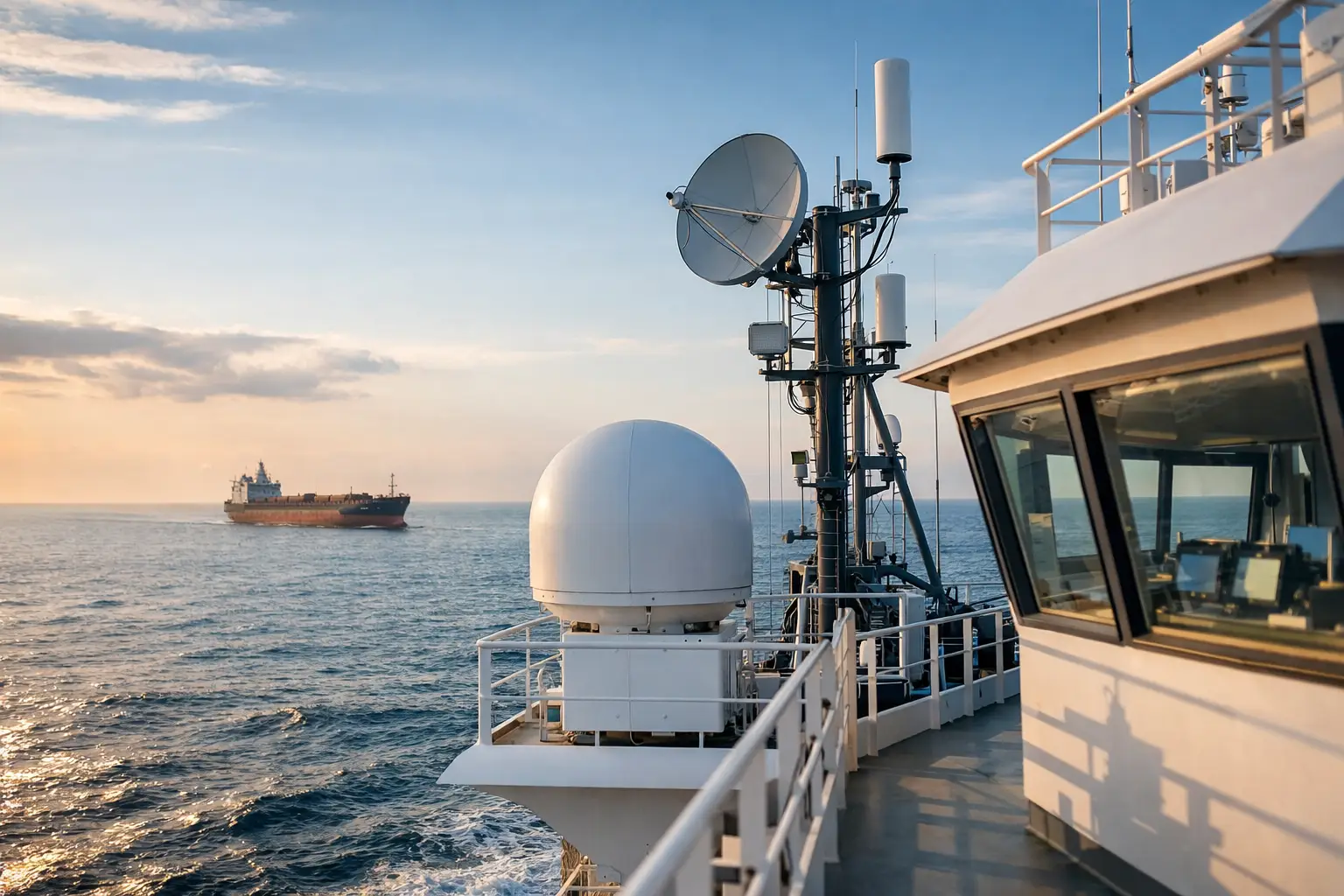
A vessel can have excellent onboard equipment and still lose operational capability because the connectivity design assumed a stable shore-side network. That assumption fails as soon as the vessel leaves port, turns behind terrain, enters a congested harbor, or encounters weather that affects a marginal microwave path. Knowing how to plan vessel connectivity starts with treating communications as an operational system, not a collection of radios, antennas, and data plans.
For commercial fleets, offshore support vessels, public safety boats, defense platforms, aquaculture operations, and workboats, the right design must carry the traffic that matters at the moment it matters. That may include navigation data, engine telemetry, video, crew welfare traffic, dispatch communications, remote access, or private LTE/5G services. Each has different tolerance for delay, loss, interruption, and security exposure.
Start With the Vessel Mission and Operating Area
Connectivity planning should begin before selecting a carrier, modem, antenna, or satellite service. Define where the vessel operates, how fast it moves, what routes it follows, and what communications must continue during a loss of primary coverage.
A harbor patrol vessel operating within a defined metropolitan shoreline has a different requirement from a crew transfer vessel moving between a coastal terminal and an offshore wind farm. The first may rely heavily on private LTE, 5G, and shore-connected microwave. The second may need a layered architecture that transitions among cellular, stabilized point-to-point microwave, and satellite backhaul without disrupting priority applications.
Map the operating area in practical terms. Include dock locations, channels, offshore platforms, wind turbines, work zones, known coverage gaps, terrain obstructions, and the distance from possible shore-side communications sites. Radio coverage maps are useful, but they do not replace a path study. A coverage claim does not account for vessel roll, antenna height, shoreline clutter, traffic congestion, or a signal path blocked by port infrastructure.
Define three operating states: in port, near shore, and beyond reliable terrestrial coverage. Then establish the minimum communications capability required in each state. A vessel does not need identical bandwidth everywhere, but it does need predictable behavior when capacity drops.
How to Plan Vessel Connectivity by Traffic Priority
The most expensive design mistake is sizing a vessel network around total bandwidth without classifying traffic. A broadband connection can appear healthy while critical applications suffer because crew streaming, cloud synchronization, or CCTV uploads consume the available uplink.
Separate traffic into operational, safety-critical, business, and welfare categories. Operational traffic may include SCADA, propulsion data, electronic chart updates, asset tracking, and remote technical support. Safety-critical traffic can include voice, emergency messaging, live incident video, and command-and-control applications. Business traffic covers administrative systems, while welfare traffic includes crew internet access.
These categories should drive quality-of-service policies, not simply reporting. Priority traffic needs reserved capacity, controlled latency, and defined failover behavior. Lower-priority traffic should be rate-limited or deferred when the vessel is on a constrained connection.
Video deserves special attention. A single high-resolution camera stream can consume more capacity than navigation, telemetry, and voice combined. Determine whether live video is always necessary, whether event-triggered transmission is sufficient, and whether recordings can be stored locally for later upload. The answer changes the backhaul requirement significantly.
Security is also part of traffic planning. Segment operational technology from crew and guest access. Use authenticated access, encrypted management paths, firewall policies, and monitoring that can identify abnormal traffic before it affects vessel operations. Connectivity should extend the vessel network without exposing core systems to unmanaged devices or public internet threats.
Build a Layered Backhaul Architecture
No single wireless technology is the correct answer for every vessel route. A practical vessel design uses the strongest available transport for the operating area and retains alternatives for continuity.
Near shore, private LTE/5G and carrier cellular can deliver cost-effective capacity when coverage is engineered and antenna placement is correct. Private cellular is particularly valuable for controlled waterfronts, ports, offshore facilities, and defined marine corridors where the operator can manage coverage, subscriber access, and application performance.
For longer near-shore routes, stabilized microwave systems can provide high-capacity backhaul to shore sites, platforms, or relay points. The key word is stabilized. A vessel is constantly moving in pitch, roll, yaw, and heading. A conventional directional antenna will not hold a narrow beam reliably under those conditions. Auto-aiming, tracking capability, and path calculation are required to maintain a usable link while the platform moves.
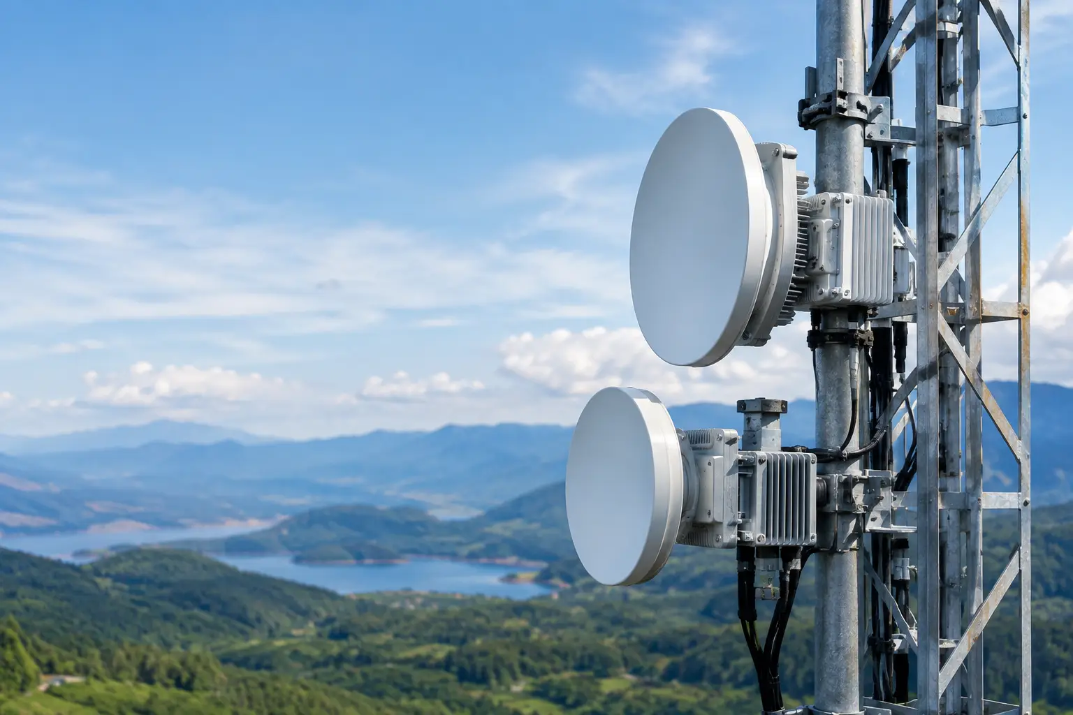
Microwave can deliver substantial capacity and low latency, but it depends on line of sight, route geometry, and correctly engineered shore infrastructure. It is not a substitute for satellite on open-water routes, and satellite is not always an economical substitute for high-volume coastal backhaul. The appropriate mix depends on distance, availability requirements, traffic volume, and the cost of interruption.
Satellite provides geographic reach and is often the final layer for offshore continuity. However, its service characteristics vary by provider, orbit, terminal type, weather conditions, contention, and regional availability. Plan for realistic committed performance rather than headline throughput. Define which applications remain available on satellite and which are paused or tightly controlled.
A multi-WAN router or SD-WAN edge can manage policy-based path selection across cellular, microwave, and satellite links. But automated failover only works when health checks test the applications that matter. A device that merely pings a public IP address may report a healthy connection while a VPN, dispatch server, or cloud platform is unreachable.
Engineer Antennas for Motion, Obstruction, and Access
Antenna selection and placement determine whether the network performs as designed. Onboard installations must account for mast height, radar exclusion zones, metal obstructions, cable loss, vibration, salt exposure, and maintenance access. An antenna installed in the highest available position is not automatically the best choice if crane booms, exhaust stacks, radar arrays, or other structures regularly block its path.
For mobile directional links, calculate the required tracking range, acquisition time, beamwidth, and stabilization performance. Narrower beams can improve link budget and reduce interference, but they demand more precise pointing. Wider beams can tolerate greater movement but may reduce range or capacity. This is an engineering trade-off, not a catalog comparison.
Use marine-rated components, appropriate sealing, corrosion-resistant mounting hardware, and strain relief for every exterior cable run. A well-designed RF path can be compromised by poor connectors, water intrusion, or an installation that cannot be inspected without taking the vessel out of service.
Design the Onboard Network as a Managed System
Backhaul is only one part of vessel connectivity. The onboard LAN must distribute service reliably to bridge systems, crew areas, cameras, machinery spaces, wireless access points, and any connected operational equipment.
Segment the network using separate VLANs or logical zones for bridge operations, OT systems, video, corporate applications, crew welfare, and guest access. Apply policies at the network edge so that a compromised or misconfigured device cannot consume critical bandwidth or access protected systems.
Use managed switching, monitored power distribution, and equipment enclosures suitable for the vessel environment. Include local logging and remote management, but avoid a design that becomes unmanageable when the remote link is unavailable. Technicians should be able to diagnose basic faults onboard, and the system should preserve enough telemetry to support shore-side troubleshooting once connectivity returns.
Power resilience matters as much as RF resilience. Identify which devices must remain online during generator transfers, maintenance events, or reduced-power operation. UPS capacity should protect the communications chain, including routers, switches, radios, tracking controllers, and any local servers supporting priority applications.
Test the Network Against Real Operating Conditions
Commissioning at the dock is necessary, but it is not proof of vessel performance. Test on representative routes, at expected vessel speeds, during turns, near obstructions, and at the edges of terrestrial coverage. Measure throughput, latency, packet loss, failover time, antenna reacquisition behavior, and application availability.
Test failure scenarios deliberately. Disconnect the primary backhaul, simulate weak cellular service, interrupt one radio path, and confirm that priority traffic continues according to policy. Verify that video is throttled, crew traffic is controlled, and operational applications retain access when capacity is limited.
Document the expected performance envelope. Network operations teams and vessel crews need to know what is normal in each coverage zone, which path is active, and when a condition requires action. This prevents a predictable reduction in offshore capacity from being treated as an unexplained network fault.
The strongest vessel connectivity plan is one that accepts changing conditions and defines a controlled response to them. When the architecture is built around mission priorities, engineered RF paths, stabilized tracking, and tested failover, the vessel remains connected in a way that supports the work rather than merely supplying internet access.
October 10, 2026

October 10, 2026

October 10, 2026

October 10, 2026
