Antenna Path Calculation for Wireless Links
Antenna path calculation for wireless links helps prevent signal loss, poor Fresnel clearance, and unstable throughput in demanding deployments.


If a wireless link looks good on paper but fails in the field, the problem is often not the radio. It is the path. Antenna path calculation for wireless links is the engineering step that tells you whether a proposed connection can actually carry the traffic, uptime, and range your operation requires under real conditions.
For enterprise and mission-critical deployments, that distinction matters. A marina backhaul, a mobile command post, a windfarm aggregation link, or a temporary construction network may all show nominal line of sight on a map. That is not enough. Reliable performance depends on terrain, Fresnel clearance, antenna height, frequency, gain, EIRP, receive sensitivity, environmental clutter, and, in many cases, movement. Good path work reduces surprises before the first mast is raised.
What antenna path calculation for wireless links actually covers
At a basic level, path calculation answers four questions. Can the antennas see each other clearly, how much signal will arrive at the far end, what margin remains after losses and fading, and how stable will the link be in the operating environment.
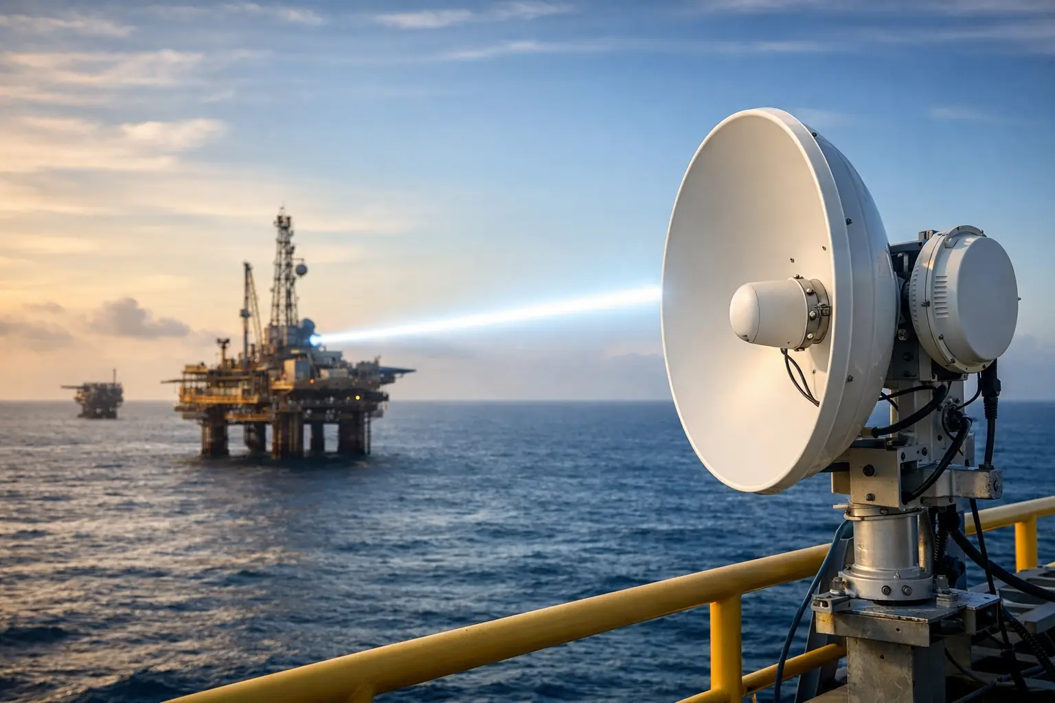
That sounds straightforward until the site gets complicated. Over water, reflections can create multipath issues even when line of sight is open. In industrial areas, cranes, conveyors, tanks, and structural steel can intrude into the path. In public safety or defense scenarios, the challenge may be a rapidly deployed link where the endpoint is mobile or the mounting surface is unstable. The geometry may work in a static model but fail once the platform pitches, rolls, or changes heading.
This is why experienced engineers do not treat path calculation as a box-checking exercise. It is a design discipline tied directly to availability, throughput, and lifecycle cost.
The core inputs that determine link viability
Every path study starts with distance and frequency, because free space path loss rises with both. As frequency increases, beamwidth narrows and alignment precision becomes more critical. Higher bands can deliver significant capacity, but they are less forgiving of obstruction, atmospheric attenuation, and mount instability.
Antenna height is the next major lever. In many projects, a few additional feet of elevation can clear a terrain bulge or improve Fresnel zone clearance enough to change the result from marginal to usable. That said, more height is not always better. Taller structures can introduce sway, wind loading, permitting complexity, and added installation cost. The right height is the one that balances RF performance with mechanical and operational reality.
Antenna gain and pattern also matter. Higher gain improves link budget, but it typically narrows the beam. On a fixed, well-engineered point-to-point link, that trade-off is often worthwhile. On a moving platform or in a deployment where precise alignment cannot be guaranteed, a slightly wider pattern may produce better real-world reliability.
Then there are the losses engineers cannot ignore: connector loss, feeder loss, radome effects, waveguide loss where applicable, and polarization mismatch. These may look small individually, but together they can consume valuable fade margin. In a long-range link, a few overlooked decibels can be the difference between stable service and repeated outages.
Line of sight is only the beginning
One of the most common mistakes in antenna path calculation for wireless links is treating visible line of sight as a final answer. A path can appear open while still being compromised by Fresnel zone obstruction.
The first Fresnel zone represents the volume around the direct path that should remain largely clear to avoid destructive interference. If terrain, vegetation, buildings, or moving objects intrude too deeply into that zone, signal quality can degrade even though each antenna can technically see the other. This is especially relevant in rural broadband extension, coastal routes, and industrial corridors where the direct line may be unobstructed but the surrounding RF space is not.
Earth curvature also becomes relevant on longer paths. A link that appears viable in a basic map view may not clear the horizon once curvature and local atmospheric assumptions are included. Over several miles, this can materially change tower height requirements.
Link budget is where theory meets performance
Once the physical path is understood, the next step is link budget analysis. This is where transmit power, antenna gain, path loss, system losses, and receiver sensitivity are combined to estimate received signal level and fade margin.
Fade margin deserves special attention because it reflects how much stress the link can absorb before performance drops below target. If the design goal is a business-grade connection with occasional degradation acceptable, the margin can be more modest. If the requirement is operational continuity for public safety, offshore operations, or private network backhaul supporting production systems, the margin should be materially stronger.
Capacity planning ties into this as well. A path may technically close at a given modulation rate, but only under ideal conditions. If the link needs to sustain committed throughput during weather events or interference episodes, the modulation strategy and target margin should reflect that. Designing to the edge may save money on day one, but it usually costs more over the life of the network.
Real-world variables that change the answer
Field deployments rarely behave like clean lab models. Water paths can introduce significant reflection and ducting effects. Forested paths may change seasonally as foliage density shifts. Temporary construction networks can lose clearance when equipment or materials are staged near the route. Oil and gas sites may add metallic structures that were not present during the original survey.
Mobility makes path calculation more demanding. Onboard communications, stabilized microwave systems, and auto-aiming applications must account for platform movement, heading change, vibration, and intermittent obstruction. In these environments, the question is not just whether the path can be closed. It is whether it can be maintained dynamically without constant manual intervention.
That is where path analysis intersects with tracking and stabilization. If the platform moves, a narrow-beam, high-capacity design can still be the right choice, but only if the antenna system can hold alignment. Without that capability, a theoretically excellent path can become operationally fragile.
Why path calculation should drive equipment selection
Too many projects start with a preferred radio or antenna and then try to force the path to fit. In practice, the path should drive the architecture.
A shorter obstructed route may favor a lower frequency and different antenna geometry. A long clean route may justify higher gain dishes and narrower beams. A maritime deployment may require stabilized antennas and integrated radios designed for constant motion and corrosion exposure. A rapid-deployment public safety network may prioritize setup speed, survivability, and interoperability over maximum spectral efficiency.
This is also where compatibility matters. The antenna, mount, tracking system, radio, and power design must work as one system. Path calculations that ignore mechanical stability, radio behavior, or platform constraints often produce designs that are mathematically valid but operationally weak.
Common planning errors that create avoidable failures
The first error is underestimating clutter. Engineers may model terrain accurately while missing trees, structures, cranes, vessel traffic, or future site development. The second is designing with insufficient fade margin, especially in links expected to support business-critical traffic.
The third is assuming a fixed-site mindset in a mobile or unstable environment. A dish that performs well on a rigid tower may not perform the same on a mast mounted to a vehicle, vessel, or temporary structure. The fourth is failing to revisit the path when requirements change. More bandwidth, a new frequency plan, or a relocated endpoint can all alter viability.
The last is treating installation accuracy as guaranteed. Very narrow beams reward precision, but they also punish rushed alignment, weak mounts, or poor stabilization. Path design should reflect actual field conditions and installer tolerances, not ideal assumptions.
What a good engineering process looks like
A disciplined path workflow begins with the operating requirement, not the hardware list. Define availability targets, traffic expectations, environmental exposure, mobility profile, and deployment constraints. From there, model the route with realistic terrain and clutter assumptions, evaluate Fresnel clearance, and build a link budget with honest losses and target fade margin.
Then pressure-test the design. What happens in rain, at maximum range, during vessel motion, or when a temporary obstruction enters the near field? Can the system recover automatically? Does the chosen antenna pattern match the alignment capability of the platform? If the answer depends on perfect conditions, the design is not finished.
For organizations deploying in harsh or mobile environments, this is where specialized engineering creates value. BATS Wireless operates in exactly these scenarios, where antenna performance, tracking, and path integrity have to hold up outside a static tower model.
The best wireless links are not just connected. They are engineered to stay connected when terrain, weather, motion, and operational pressure start working against them. That is what path calculation should deliver before the deployment ever leaves the ground.

June 8, 2026
June 8, 2026

June 8, 2026

June 8, 2026
